Thermal Interface Material Selection Guide
Heat leaves a device through a chain of materials, and every joint in that chain is a pair of surfaces pressed together. Two nominally flat surfaces touch only at the tops of their roughness peaks, so most of the apparent contact area is filled with air, and air conducts heat about forty times less effectively than a polymer and thousands of times less effectively than copper. A thermal interface material exists to displace that air and to replace it with something better.
This article explains why the interface dominates a thermal path, what the material families offer, which parameters decide the choice, and how the material is applied and verified.
Why The Interface Dominates
The thermal resistance of an interface is the sum of the resistance of the material layer and the resistance of the two contact surfaces. The material contribution is the bond line thickness divided by the conductivity, so a thin layer of a mediocre material can outperform a thick layer of a good one. That single relationship explains most of the practical rules: apply the material thinly, apply enough pressure to reduce the bond line, and choose a material that stays in place at the operating temperature.
The magnitude is worth an example. A gap of a tenth of a millimetre filled with air has a resistance of roughly four degrees per watt across a square centimetre, while the same gap filled with a material of three watts per metre kelvin has a resistance of about three hundredths of that. The difference is the reason a power device that runs hot without an interface material can drop by tens of degrees once one is properly applied, and it is also the reason a badly applied interface, with a void or an excessive thickness, undoes most of the benefit.
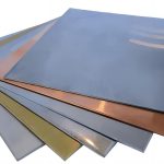
<img src="https://www.gopcba.com/wp-content/uploads/2026/06/harsh-environment.jpg" alt="Thermal pad placed between a device and a heatsink” />
The Material Families
Thermal grease is a filled silicone or hydrocarbon paste. It has the lowest thermal resistance of the common options because it can be spread very thin, but it requires clamping pressure to stay thin, it can be pumped out of the joint by thermal cycling, and it is difficult to apply cleanly in production. A gap pad is a preformed, compliant sheet, usually between half a millimetre and five millimetres thick, which is used where the surfaces are not parallel or where the gap is too large to fill with paste, and its low modulus versions need very little pressure.
A dispensed gap filler is a two part material that is applied as a bead and cures in place, which suits large, irregular, or multiple gaps on one assembly and allows a single material to serve several heights. A phase change material is a thin film that softens at operating temperature and flows into the microscopic gaps, giving a low bond line without the mess of grease. A thermal adhesive carries structural load as well as heat, and a soft metal foil such as indium gives the lowest resistance of all at a high cost.
The Parameters That Decide The Choice
Bulk conductivity is the number printed on the datasheet and the least useful one on its own. What matters is the thermal impedance of the assembled joint, quoted at a specified pressure and thickness, because that figure includes the contact resistance and the bond line that the material achieves in practice. A material that is quoted at five watts per metre kelvin at high pressure may perform worse than one quoted at three if the clip on the real assembly cannot supply that pressure.
The remaining parameters are mechanical and environmental. Hardness and modulus decide how much the material conforms at the available pressure, the thickness range decides whether a large gap can be filled at all, and the dielectric breakdown voltage decides whether the material can isolate a tab from a grounded heatsink. The operating temperature range, the tendency to dry out or to migrate, and the ease of rework complete the list. A material that meets the thermal requirement but migrates into a connector or dries out after a thousand cycles has not met the requirement.

Matching The Material To The Application
A small package clamped by a clip to a heatsink is served by a thin phase change film or a low resistance grease, because the pressure is modest and the gap is small. A large gap between an uneven component and a stamped heatsink is served by a gap pad whose modulus is low enough to conform at the pressure available, or by a dispensed filler where the gap varies across the assembly. A device that must be electrically isolated needs a pad with a dielectric rating, and a high volume line favours a material that can be dispensed or pre-applied rather than one that must be spread by hand.
The rework requirement often decides the family. A thermal adhesive makes a permanent joint and is chosen when the mechanical attachment has to come from the same material, while grease and pads allow a component to be removed and replaced. Where a device is expected to be reworked, the material should be chosen with that step in mind, because a cured adhesive has to be cut away and the pad beneath it cleaned before a replacement can be fitted. The mechanical side of the same assembly is described under board outline and mounting design.
Application And Process Control
The application method sets the bond line. A stencil printed pad, a dispensed bead, or a pre-applied film all give a defined volume, while a hand applied grease gives whatever thickness the operator produced. Pressure is the second control, because the bond line falls as the load rises, and the fixture used during cure has to hold that load until the material has set. Air entrapment during dispensing or placement produces voids, which are local hot spots, and the surfaces should be clean and free of release agents, which act as a thermal barrier themselves.
The most common error is over-application. An operator who sees a gap and fills it generously produces a thick joint with a resistance higher than the air it replaced, and the device runs hotter than it did without any material at all. The correct volume is the smallest that covers the interface and fills the surface roughness, and the assembly instruction should state it in millimetres of thickness or in milligrammes of material rather than as a visual impression. Dispensing equipment and the materials that flow through it are described under potting and dispensing adhesives.
Reliability And Measurement
Two aging mechanisms deserve attention. Pump out occurs when thermal cycling expands and contracts the two surfaces by different amounts and squeezes the grease out of the joint, which increases the resistance over time. Dry out occurs when the carrier liquid in a paste migrates away and leaves the filler behind, which also raises the resistance. Silicone migration is the third concern and it is a system level problem rather than a thermal one, because a volatile fraction that condenses on connector contacts raises their contact resistance.
Measurement closes the loop. The prediction from the datasheet is checked by measuring the case temperature of the device and the temperature of the heatsink at a defined load and ambient, and the difference between them gives the joint resistance. When the measured value is much worse than the calculated one, the usual causes are an excessive bond line, an incomplete coverage, or a clamp that is not applying the load that was assumed. The fabrication context for those interfaces is described under PCB design and fabrication.
FAQ
Is a higher thermal conductivity always better? Not by itself. The assembled resistance depends on the bond line thickness and the contact pressure as much as on the conductivity, so a thin layer of a moderate material can beat a thick layer of a good one.
Should grease be used on a large gap? No. Grease cannot bridge a large gap and will simply be squeezed out. A gap pad or a dispensed filler is the appropriate choice where the gap is more than a few tenths of a millimetre.
Why does the joint resistance rise over time? Because thermal cycling pumps the material out of the joint and because the liquid phase of a paste can dry out. Both mechanisms leave less material in the interface and increase the resistance.