Thermal Relief Design In Copper Planes
A pad that is connected directly to a large area of copper is difficult to solder, because the copper conducts heat away from the joint as fast as the iron or the oven supplies it. The usual answer is a thermal relief: a pad that is connected to the plane by a small number of narrow spokes rather than by its whole perimeter, so that the connection is electrically sound but thermally restricted during soldering. It is a simple pattern that causes a surprising amount of argument, because the same feature that helps the process hurts the electrical and thermal performance of the finished board.
This article explains what the relief does, how its dimensions are chosen, when it should not be used, and how it interacts with planes and vias.
What The Pattern Does
The relief is formed by a gap between the pad and the surrounding plane, crossed by three or four spokes. During soldering the spokes limit the rate at which heat leaves the pad, so the joint reaches the melting point of the solder without the iron having to be held on it for a long time. The gap also limits the flow of solder away from the joint, which is why the pattern is sometimes called an anti wicking feature.
On a reflowed assembly the benefit is smaller, because the whole board is heated in the oven and the pad will reach temperature eventually. The relief still helps, because it reduces the difference between a pad connected to a plane and an isolated pad, and that difference is what produces the skewed joints and the tombstoned parts seen on boards where one end of a two terminal component is on a plane and the other is on a trace.
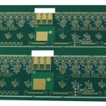
<img src="https://www.gopcba.com/wp-content/uploads/2026/08/Three-green-PCBs-with-diverse-components-prominently-displaying-LED-technology.webp" alt="Thermal relief pattern around a pad inside a copper plane” />
The Trade-Off
The restriction that helps soldering is exactly what the finished board does not want. A connection made through four narrow spokes has a higher thermal resistance and a higher electrical resistance than a direct connection, and the current that flows through the pad has to pass through those spokes. For a ground pad on a signal device the penalty is negligible; for a pad that carries several amperes or that has to conduct heat out of a power device, it can dominate the design.
There is also a noise consequence. The inductance of a narrow spoke is larger than that of a wide connection, and the impedance between the pad and the plane is what determines how well the plane can act as a reference at that point. Where a pad is a return path for a fast signal or for a switching current, the relief should be omitted, and the layout should rely on the thermal mass of the iron or on a preheated board instead.
Dimensions That Work
The classic relief has four spokes at right angles, each about half the width of the pad or a fixed value such as 0.3 to 0.5 millimetres, with a gap of the same order around the rest of the pad. Four spokes at right angles give the most even thermal behaviour and are the usual default. Where more current is needed, the spoke width is increased or a fifth spoke is added, but the number should stay odd or even in a way that keeps the pattern symmetric, because an asymmetric relief pulls solder to one side.
The gap has to be larger than the minimum spacing of the process, or the etch will not clear it reliably and the relief will short to the plane. On a heavy copper layer the gap grows to the same minimum gap that the layer supports, which is one of the reasons heavy copper boards often use no relief at all and manage the soldering with preheat instead.

When Not To Use One
There are four common cases where the relief should be left out. A pad that carries high current, a pad that is a thermal path from a device to the plane, a pad that is part of a radio frequency ground, and a pad that is a return for a fast switching current all want a solid connection. In each case the electrical or thermal requirement is more important than the convenience of the assembly process.
A practical compromise is to use the solid connection and to change the process instead: preheat the board, use a larger iron tip, extend the soak in the reflow profile or add a thermal via field under the pad so the heat is spread before it reaches the joint. Each of these addresses the same problem from the process side rather than from the artwork, and each is usually cheaper than degrading the electrical performance of the board for the whole of its life.
Planes, Vias And Heat Sinking
A relief is a decision about one pad, while the plane it sits in is a decision about the whole board. The way a plane is split, the way it is flooded and the way the return current is routed all affect how useful the relief could be, and the rules for those larger decisions are set out under power plane splitting rules, copper flooding, mesh or solid and ground routing and power trace planning.
Where a package has to lose heat, the relief is normally replaced by a field of thermal vias that carries the heat to planes on other layers and eventually to an external surface. The via field is more effective than a solid connection to one plane, because the heat has more than one path, and it is the arrangement used under the exposed pads of power devices and under the ground pads of radio frequency amplifiers.
Review And Verification
The way to catch a problem is to review the pads that carry current or heat against the pads that carry only signals. A query on the layout that lists every pad connected to a plane through a relief, sorted by the current the net is expected to carry, will find the few that matter in a few minutes. The same list is useful at first article, because a pad that solders easily and runs hot in operation is a relief that should not be there.
Verification after the fact is a thermal measurement rather than an inspection. A thermal camera on a board running at full load will show the pads that are being used as heat paths, and a joint that runs significantly hotter than its neighbours is a relief that is restricting the flow that the design assumed. The fix is a layout change rather than a process change, which is why the decision is better taken at the review than at the thermal test.
Where The Pattern Comes From
Reliefs are generated by the layout tool from a rule attached to the plane, not drawn by hand, and the rule should be attached to the plane polygon rather than to individual pads. When the rule is set on the plane, every pad that is added to that net afterwards inherits the pattern automatically, which removes the possibility of a pad that is missed and a joint that is unsolderable for a reason nobody can see. Setting the pattern per pad instead is a common practice in older libraries and it is the reason some pads on those boards have a relief and others do not.
The library also decides whether the pad is defined by its copper or by its mask opening. A mask defined pad has a copper area larger than the opening, which changes how the relief behaves, and a copper defined pad has the opening larger than the copper. Both are workable, but a design that mixes the two conventions on the same board will produce joints that behave differently under the same profile, and the assembly line will have no way to compensate for the difference.
FAQ
How many spokes should a relief have? Four, at right angles, is the usual default. Fewer spokes reduce the heat flow during soldering but increase the resistance, and more spokes remove most of the benefit of having a relief at all.
Does a relief affect the electrical performance of a ground pad? It raises the impedance between the pad and the plane slightly, which is harmless for a slow signal and significant for a fast one or for a return path carrying switching current.
Can the relief be removed for a single pad? Yes, and the layout tool normally allows the pattern to be suppressed per pad or per net, which is the cleanest way to make an exception without changing the rule for the whole board.