High-Temperature PCB: Materials and Design Considerations
A high-temperature PCB is defined by its operating range rather than by its appearance. Standard boards are rated for roughly minus 40 to plus 85 degrees Celsius. Boards intended for engine compartments, downhole instruments, industrial ovens or power conversion equipment must keep working from 125 degrees Celsius upward, and some ceramic assemblies operate near 300 degrees Celsius.
Temperature changes almost every material decision. The laminate, the copper, the solder alloy, the solder mask and the components all have temperature limits, and the assembly is only as good as the weakest of them.
What Makes a Board High Temperature
The rating comes from the glass transition temperature of the laminate and from the decomposition temperature of the resin system. A standard FR-4 laminate with a glass transition near 130 to 140 degrees Celsius softens and expands quickly above that point, and the expansion tears plated barrels in vias.
High-temperature laminates raise the glass transition above 170 degrees Celsius, with polyimide systems reaching 250 degrees Celsius or more. The higher the transition temperature, the more stable the dimensions through thermal cycling, and the longer the plated through-hole survives repeated excursions.
It is not only about peak temperature. A board that cycles between cold and hot a thousand times sees mechanical fatigue rather than simple heat damage, and the coefficient of thermal expansion along the thickness axis determines how much strain each via barrel absorbs.
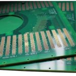
<img src="https://www.gopcba.com/wp-content/uploads/2024/10/pcb-coloro.jpg" alt="High-temperature PCB with ceramic substrate and heavy copper” />
Substrate Materials and Where They Fit
Polyimide is the most common high-temperature PCB substrate. It keeps its mechanical and electrical properties to about 250 degrees Celsius, resists chemicals and moisture, and is available in thin laminates that suit both rigid and flexible constructions.
A ceramic substrate takes the next step. Alumina and aluminium nitride carry very high temperatures, have excellent thermal conductivity and hold dimensions tightly, which is why they are used for high-frequency and high-power circuits. The trade-off is cost, brittleness and a maximum practical board size.
PTFE covers the upper range for radio frequency work. It tolerates temperatures up to about 300 degrees Celsius and has very low dielectric loss, so it is chosen when both heat and high-frequency performance matter. Its mechanical softness makes processing more delicate than FR-4.
Thermal Expansion and Via Reliability
Thermal expansion in the thickness direction is the mechanism that destroys vias. Copper expands at about 17 parts per million per degree Celsius, while a typical laminate expands at 50 to 70 parts per million below its glass transition and much more above it. The difference is taken up by the copper barrel.
Below the glass transition, a plated barrel can usually absorb the strain. Above it, expansion rises sharply and the barrel eventually cracks, which appears as an intermittent open that only shows up when the board is hot. High-temperature laminates reduce the expansion above the transition, which is why they extend via life.
Design responses include thicker copper plating in the barrel, larger pads to distribute stress, and avoiding vias with a high aspect ratio. Where a design must use a small via in a high-temperature application, filled and capped vias remove the barrel from the strain path entirely.
Solder Alloy and Joint Reliability
Solder alloy choice follows the operating temperature. A lead-free SAC305 joint melts near 217 degrees Celsius and is normally used below about 125 degrees Celsius continuously. Above that, the joint creeps under load and thermal cycling begins to crack the interface.
Higher-temperature alloys such as those containing bismuth or antimony raise the melting point and improve creep resistance at elevated temperature, at the cost of a higher reflow peak and narrower process window. Gold-tin and other high-melting alloys appear in die attach and in assemblies that must survive above 200 degrees Celsius.
Whatever alloy is chosen, the reflow profile must be redeveloped rather than inherited. A high-temperature laminate has a different thermal mass and a tighter maximum ramp rate, and the assembly drawing should state the peak temperature the laminate can tolerate.
Solder Mask, Silkscreen and Surface Finish
The solder mask must survive the same temperature as the laminate. Standard photosensitive masks degrade and lose adhesion above about 150 degrees Celsius, so high-temperature formulations are used where the board sees continuous heat. Adhesion loss at a pad edge is the beginning of a short.
Surface finish affects joint formation. Hot air solder levelling has a relatively low temperature limit, while electroless nickel immersion gold and immersion silver tolerate higher process temperatures and store better. For repeated thermal cycling, the finish must remain solderable after the first reflow.
Layout Rules for Hot Environments
Spread heat instead of concentrating it. Thermal vias under power devices move heat to internal copper, and heavy copper on the outer layers spreads it sideways. Keeping the heat-generating parts away from the laminate edge reduces the peak temperature at the board outline.
Design for expansion. Use wider traces and larger annular rings, avoid sharp copper corners where a crack can start, and keep the stackup symmetrical so that the board does not bow as it heats. Distances between a via and a plane edge should be generous, because the two materials move differently.
Consider the enclosure as part of the thermal design. A board bolted to a metal chassis conducts heat away far better than one standing in still air, and the mounting pattern should be chosen so that the hottest area is close to the highest-conductivity path.
Component and Life Considerations
Components limit the assembly as often as the board does. Electrolytic capacitors dry out, plastic packages absorb moisture and reflow-sensitive parts crack during assembly. Where a board must run hot for years, the component list is reviewed for rated temperature and derated accordingly.
Life expectancy follows the Arrhenius relationship, roughly doubling for every ten degrees of temperature reduction. That single fact explains why thermal design in a high-temperature PCB is a reliability activity rather than a performance one: running a joint thirty degrees cooler can multiply its life eightfold.
Related reading: conformal coating and board protection, via in pad versus plated through, and multilayer prototype requirements.
Testing and Qualification
High-temperature assemblies are verified at temperature, not at room temperature. Functional test at the maximum operating temperature reveals opens that close when the board cools, and thermal cycling between the extremes exposes barrel fatigue before it reaches the field.
Where the application is safety related, the board may also be subjected to humidity, vibration and insulation resistance checks. The test plan belongs in the documentation, because a board qualified to one set of conditions cannot be assumed qualified to another.
FAQ
Can a standard FR-4 board be used above 125 degrees Celsius? Only briefly and with derating. Continuous operation above the glass transition causes expansion, barrel strain and eventual via cracking, and the failure appears as an intermittent open that only occurs when the board is hot.
When is a ceramic substrate justified? When thermal conductivity, dimensional stability or very high operating temperature matters more than cost. Ceramic also performs well at high frequency, which is why it appears in power and RF assemblies rather than in general logic.
Does a higher melting solder alloy solve thermal problems? It raises the temperature the joint can survive, but it also raises the reflow peak and narrows the process window. It is one part of the answer, alongside laminate choice, via design and thermal spreading.