112G PAM4 Channel Design Rules and Loss Budget
When a serial link reaches 112G PAM4, the Nyquist frequency lands at 28 GHz. At that point the printed circuit board stops behaving like a set of connected wires and starts behaving like a microwave network. Every discontinuity that was tolerable at 25 Gbps becomes a measurable penalty: a via, a trace corner, a change in reference plane, the roughness of the copper foil, and the weave of the glass cloth inside the laminate.
The same generation of equipment also has to carry serious current. Automotive platforms moving to 800 V architectures need boards that hold high voltage clearances while conducting hundreds of amperes in the battery and inverter paths. Designing for both extremes on one product is where the difficulty lies, and it is why the loss budget and the clearance rules have to be decided before layout begins.
The Insertion Loss Budget at 28 GHz
The governing limit for a 112G PAM4 channel is a total insertion loss of no more than 28 dB at the 28 GHz Nyquist frequency, as defined for the relevant Ethernet channel specification. Because the budget is total, it must be divided among the package, the connector, the trace, the vias and the receiver equalisation margin. Anything that consumes loss has to be accounted for, and there is very little room for a structure whose contribution was never evaluated.
That is what makes the microscopic features matter. A trace corner that produces a small impedance discontinuity reflects a fraction of the signal; a via with a stub radiates energy at its resonance; a rough copper surface increases conductor loss as frequency rises because the current is squeezed into the surface and forced to follow the profile. Copper foil roughness in particular is often ignored in low-speed designs and becomes a first-order term at these frequencies.
<img src="https://www.gopcba.com/wp-content/uploads/2025/05/未标题-6.jpg" alt="112G PAM4 channel routed on an ultra-low-loss laminate stackup” />
Via Structures and Deep Microvias
At these data rates the via is not a simple connection but a resonant structure. A through via that carries a signal from the top layer to an inner layer leaves an unused stub, and that stub produces a sharp increase in loss at its resonant frequency. Removing the stub, whether by back-drilling after plating or by using blind and buried vias that terminate at the required layer, is usually the cheapest way to recover bandwidth, as described in the rules for back-drilling a PCB.
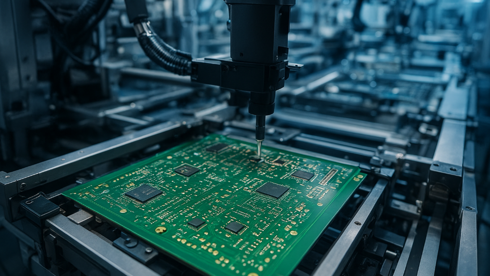
High-density interconnect boards used for these channels also employ deep microvias, drilled by laser from the first layer through to the third or even the fourth. Producing them reliably demands control of laser energy, of the dielectric surface after ablation, and of plating uniformity inside a small, deep feature. A plating thickness that varies around the barrel changes the local impedance, and a small impedance mismatch at a via can consume a disproportionate share of the loss budget. The structural options are described in high density interconnect design.
Choosing an Ultra-Low-Loss Laminate
Material selection narrows quickly at 28 GHz. Standard high-speed laminates lose too much energy at microwave frequencies, and once a channel exceeds roughly five inches of trace length, an ultra-low-loss laminate becomes necessary rather than optional. The decision is driven by the dissipation factor of the dielectric, which sets dielectric loss, and by the copper foil used on the laminate, because foil roughness adds conductor loss that no equaliser can remove.
Two secondary effects are easy to overlook. The first is the glass weave of the laminate: the resin and the glass cloth have different dielectric constants, so a differential pair that runs along the weave can see a different velocity on each trace, producing skew and mode conversion. The second is the loss characteristic across frequency, which determines how much the equaliser has to correct and therefore how much margin remains. Both are reasons to specify the material by measurement data rather than by a category name.
<img src="https://www.gopcba.com/wp-content/uploads/2024/09/d72fc51735905611378fa8e31dee527-1536×1152-1.webp" alt="High voltage clearance and creepage distance marked on a power board” />
The High-Current Side: 800 V and Creepage
While the signal side is chasing bandwidth, the power side is chasing current and voltage at the same time. An 800 V traction architecture raises the clearance requirements considerably: under the applicable creepage and clearance rules, the spacing needed between conductors at that working voltage roughly doubles compared with a lower-voltage design, and that spacing must be maintained across the board, not only at the connectors.
The failure mode that ties high voltage to the PCB material is conductive anodic filament growth, a migration of copper through the laminate that can bridge two conductors under the combined influence of voltage, moisture and ionic contamination. It is a particular risk in fast charging and inverter boards, where the dielectric must withstand the field for years. Specifying a laminate with verified high-voltage performance, controlling moisture during assembly and keeping the surface clean are the practical countermeasures.
Copper Buildup for High Current
Carrying hundreds of amperes through a board requires more copper than a standard one-ounce layer provides. The two usual approaches are heavy copper layers, often several ounces thick, and embedded copper pieces that are laminated into the board and carry the main current in a solid bar. Both reduce the resistive path, but they change the fabrication process: heavier copper etches differently, with a coarser minimum feature size, and embedded pieces require a cavity in the stackup and careful control of resin flow around them.
The design consequence is that the copper weight must be decided with the stackup, not after the layout. Minimum trace width and spacing on a heavy-copper layer are wider than on an inner signal layer, and the thermal relief around a pad in a thick copper plane behaves differently during soldering. Where the high-current path meets a signal net, the discontinuity must be managed with the same discipline as the high-speed side, because a large change in geometry is a reflection as well as a resistance.
Verification Before Release
The two halves of the design are verified with different instruments. High-speed channels are checked with impedance measurements along the trace, insertion loss and return loss from a coupon or a finished trace, and an eye diagram at the target rate. Compliance also requires the channel to meet impedance discontinuity limits at every via and layer transition, which is where the analysis in low loss laminate selection becomes an input to the measurement plan.
The power side is checked with voltage drop measurements under full load, thermal imaging of the conductors and insulation tests at the working voltage. Both sides depend on fabrication quality, because plating thickness and dielectric uniformity affect the electrical result as much as the layout does.
FAQ
Why is 28 dB of insertion loss so difficult to meet? Because the budget covers the whole channel, from package to receiver, at the Nyquist frequency. Vias, connectors, foil roughness and the dielectric all consume part of it, so a single uncompensated structure can exhaust the margin that the equaliser depends on.
How is creepage distance set for an 800 V board? It is derived from the working voltage, the pollution degree and the material group of the laminate under the applicable standard, and it roughly doubles compared with a low-voltage design. The value must be maintained over the whole board surface, including under components and at the connectors.
Can a high-speed channel be routed on a heavy-copper layer? Rarely, because heavy copper forces a coarse minimum feature size and a thicker, less controlled dielectric. High-speed routing belongs on fine-line layers of the stackup, and the two domains should be separated as described in PCB manufacturing tolerances.