eVTOL PCBA Certification: What Airworthiness Rules Change
China’s revised Civil Aviation Law took effect on 1 July 2026 and extended explicit airworthiness permit requirements across the design, production, import, maintenance and operation of civil unmanned aircraft, together with a rule that manufacturers assign a unique product identification code to each aircraft. Supporting documents, including a new type certification procedure, followed at the same time. Nineteen civil unmanned aircraft had already obtained type certificates before the change, so the framework now applies to a market that is moving from demonstration flights toward certified products. Bringing that assembly inside the compliance case is exactly what eVTOL PCBA certification now requires from every supplier in the chain.
For the electronics supply chain, eVTOL PCBA certification is now the governing constraint rather than a future concern. The significance is not that low altitude aviation has a legal basis. It is that flight electronics now sit inside a certification and continued airworthiness system that follows the aircraft through its entire service life. A printed circuit board assembly stops being a purchased component and becomes part of a traceable safety argument, which changes how it must be designed, built and documented.
A Legal Change With Engineering Consequences
Airworthiness requirements propagate downward. If the aircraft has to demonstrate continued safe flight under defined failure conditions, each electronic function has to be classified by the effect of its failure, and the classification determines the design measures applied to it. A function whose loss is catastrophic needs redundancy or a demonstrated failure rate low enough to be acceptable, and those measures reach the board level as duplicated channels, isolation between channels and independence in power and signal routing.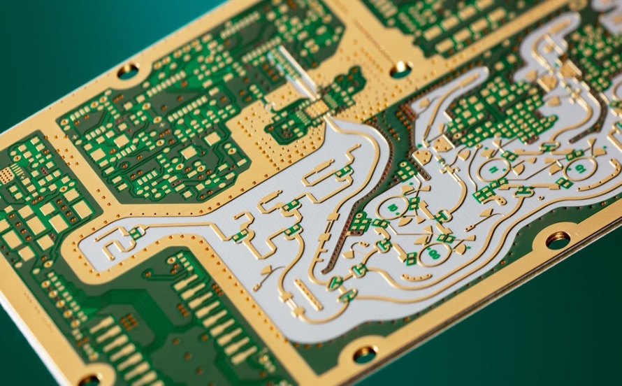
That is why certification has more effect on layout than on component selection. Two identical circuits placed on the same board are not automatically redundant if they share a power rail, a connector or a region of the ground plane where a single fault can disable both. Demonstrating independence is a layout and assembly question, and it has to be designed in from the start rather than reviewed at the end.
Automotive Experience Helps, but Tolerance for Failure Differs
Electric vertical takeoff aircraft share a great deal with electric vehicles. Both need battery management, motor control, power conversion, sensor fusion and a central controller, and the automotive industry has already invested heavily in high current design, functional safety practice and volume reliability. That experience transfers directly to many parts of an eVTOL electronic architecture, and it is the main reason the supply chain can start from a mature base.
The difference is what happens after a failure. A road vehicle can usually be brought to a stop or degraded to a limited mode, so some failures are survivable. An aircraft in flight may have no equivalent option, so systems are typically designed to keep operating after a failure rather than to shut down safely. That single change raises the requirement on connectors, solder joints, thermal margin and power continuity far beyond what an automotive equivalent would demand.
Power Electronics: Current, Heat and Weight Together
Electric propulsion moves large currents through the board at voltages chosen to keep those currents manageable, and the copper that carries them also has to remove heat. Thick copper layers, thermal vias and in some cases embedded busbars are used together, and the thermal path has to be considered as a system that includes the enclosure rather than as a property of the board alone.
Weight then constrains every one of those measures, because an aircraft cannot simply add copper and heatsinking. Design proceeds by trading current capacity, thermal performance, reliability and mass until all four are acceptable, which makes power electronics for low altitude aviation closer to a system engineering exercise than a straightforward high current layout. Because the margin for error is small, verification of assembled board testing and thermal behaviour under load has to happen before the design is frozen.
Flight Control and Perception in a Small Envelope
The second electronics cluster is flight control, navigation and perception. A flight controller continuously processes inertial measurement data, satellite navigation, radar or lidar returns, camera images, barometric pressure and motor status, and the number of sensors keeps rising as autonomy increases. More sensor data means more high speed interfaces inside a smaller enclosure.
High speed signalling raises requirements on impedance consistency, loss and electromagnetic compatibility, while the enclosure limits board area. High layer count and HDI constructions are therefore common, and designers have to manage return paths carefully to keep sensitive analogue and radio frequency sections isolated from switching noise. The combination of high speed and constrained space is the defining constraint on the avionics board rather than any single specification.
Flex and Rigid-Flex Trade Harness Weight for Mechanical Risk
Wings, arms and sensor pods are connected through structure that flexes in service, and conventional wiring harnesses are heavy and take up volume. Flexible and rigid-flex circuits reduce connector count and replace cable runs with laminated conductor paths, which saves mass and improves repeatability of assembly.
The trade is mechanical. Flex sections experience continuous vibration and repeated bending, and the transition zone where a rigid board meets a flex tail concentrates stress. Design rules for bend radius, coverlay openings, conductor orientation relative to the bend and stiffener placement determine whether the assembly survives the flight envelope. Programs that treat flexible circuits as ordinary cables usually discover this during vibration testing, which is an expensive place to learn it. Working with a supplier experienced in flexible circuit assembly from the prototype stage avoids most of those surprises.
Traceability From Aircraft ID Down to Batch Records
The unique product identification code applies to the aircraft, not to each circuit board, but it changes the expectations placed on the supply chain. If an aircraft is traceable through its life, the electronic assemblies inside it need records that connect a serial number to the batch of laminate, the components used and the test results obtained. When a defect is found in service, that chain is what allows an operator to determine which units are affected.
Building that chain is an operational capability rather than a document. It requires lot control at incoming inspection, serialisation at assembly, and test data retained against the unit rather than against the work order. Suppliers to this market are usually asked to demonstrate the system before they are asked to demonstrate a product, which is a different evaluation from the one used in consumer electronics. It is the natural extension of an established quality management system.
Proving Production Readiness Before a Program Ramps
A prototype that flies is not evidence of production capability. Certification authorities look at whether the manufacturing process produces consistent units, which means process capability data, controlled changes, defined special processes such as lamination and conformal coating, and evidence that those processes are monitored.
For a board supplier this is the point where engineering support becomes part of the deliverable. Changes to a qualified assembly have to be assessed for their effect on the safety argument, which is only practical if the supplier keeps process records detailed enough to answer the question. Programs that select a manufacturer early, involve them in capability planning before design freeze and keep the process history under configuration control spend far less time in certification than those that treat manufacturing as a later purchase.
Environmental Qualification Reaches Every Solder Joint
Flight hardware is qualified against temperature extremes, rapid thermal change, vibration, humidity and reduced pressure, and those stresses act on the assembly rather than on the silicon. Solder joints on heavy components experience mechanical load during vibration, ceramic parts are sensitive to thermal cycling, and conformal coating has to protect the surface without trapping contaminants underneath.
The practical consequence is that component selection and layout are reliability decisions. Large components are placed away from high deflection areas, leadless packages are avoided where thermal cycling is severe, and stiffeners or underfill are used deliberately rather than as a late remedy. Because these choices are difficult to change after qualification, they belong in the design review that precedes layout release rather than in the test campaign that follows it.
Connectors, Harnesses and Second Sources
Certified aircraft tend to stay in production for many years, and the electronic assemblies inside them have to remain available for that period. That raises the question of second sources for components and connectors well before a program reaches volume, because a part that becomes obsolete during certification can stall the entire compliance case.
Connector selection deserves particular attention, since it combines mechanical retention, contact resistance and current carrying capacity with the requirement that the mating interface remain stable under vibration. A connector qualified in a laboratory environment may behave differently in an airframe, and the remedy is usually a locking mechanism, strain relief and a defined routing that prevents load from reaching the contacts. Documenting those decisions inside the configuration record is what allows the aircraft to be maintained years later without re-deriving the original reasoning.
What Comes Next
The near term driver is the number of programs entering type certification rather than the number of aircraft delivered. Each of those programs has to build a compliance case that includes electronic hardware, and the supplier that can produce documented, repeatable assemblies will be the one that stays in the supply chain as volumes rise. Price competition will matter later, once designs are stable.
For engineering teams, the practical implication is that airworthiness requirements should influence the first schematic and the first stack up, not the final test report. Redundancy that can be demonstrated, thermal margin that is measured rather than assumed, mechanical design that survives vibration and a traceability chain that can be audited are all cheaper to build in at the beginning. Assemblies designed that way are also, conveniently, assemblies that pass the manufacturing process with fewer rework loops.