800G Optical Module PCB: mSAP, HDI and Yield Discipline
On 3 September 2026 a Chinese securities firm published its first research note on a listed PCB manufacturer, and the numbers inside it describe a market that has changed phase. The company had qualified with several mainstream server and cloud customers, was shipping 800G and 1.6T optical module boards in volume, and reported second quarter 2026 revenue from 800G and faster optical module PCBs up almost fifteen hundred percent compared with the previous quarter. Composite yield on high speed optical module boards exceeded eighty five percent in the first half of the year. At its Zhuhai site the company planned five mSAP lines within the year, with three already running and the fourth and fifth being installed. An 800G optical module PCB is where that density requirement lands, and where the manufacturing difficulty concentrates.
Every 800G optical module PCB now carries more high speed channels in the same package, so a quarter on quarter increase of that size is not a demand signal but an industrialization signal. Optical module boards have moved out of the qualification phase and into volume production, and the competition has shifted from whether a design can be built to whether the same electrical performance can be repeated across hundreds of thousands of panels.
What the Growth Rate Actually Shows
Optical modules follow the bandwidth of the switches and servers they connect. As data centre links moved to 800 gigabits per second and then to 1.6 terabits, the number of high speed channels per module rose and the board inside had to carry more signal pairs in the same package footprint. Board content per module increased faster than module volume, which is why revenue from these boards can multiply while unit shipments grow much more slowly.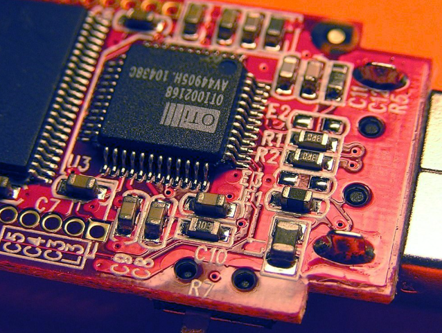
The second half of the same research note points to what comes next. Orders are still concentrated at 800G, 1.6T is ramping quickly, and the manufacturer has already begun joint development of 3.2T, near package optics and external package optics architectures. Each step raises the requirement on loss, line precision and interconnect density, so capacity built today has to be capable of serving the next generation without a new factory.
Why Optical Modules Push Board Density
A high speed optical module integrates a digital signal processor, driver devices, optoelectronic components and power circuitry in a package whose dimensions are fixed by optical and thermal standards. Component count is high, the layout area is small, and the differential pairs connecting them have to maintain impedance continuity and low loss from the processor to the optical interface.
The design escape routes are limited. Traces cannot simply be made wider and longer to make manufacturing easier, because that increases loss and consumes routing space. Adding layers increases thickness, which conflicts with thermal paths and package height, and adds interlayer via transitions that perturb impedance. The remaining option is higher routing density, and that is the option that pushes optical module boards toward fine line fabrication and advanced HDI. It is also why the value of these boards depends on how many high speed connections can be packed per unit area rather than on how much laminate they contain.
mSAP Moves From Specialty Process to Volume Capacity
Modified semi-additive processing builds conductors by plating into a pattern rather than by etching away unwanted copper, which reduces the side etch that limits the achievable line width and spacing in conventional subtractive etching. For very fine lines, that difference determines whether a design can be produced at all with acceptable yield.
The manufacturer in question installed its first mSAP line in 2022 and has judged that optical module mSAP capacity could become a bottleneck, which explains the expansion to five lines. That sequence matters more than the technology label. A process becomes strategically important when product architecture forces it into the mainstream, and that is what has happened here: dense fanout from high pin count devices and dense high speed routing cannot be accommodated with the line widths that a general purpose factory runs.
Fine Lines, Microvias and Impedance Together
Fine line capability alone does not make a module board manufacturable. The same product combines fine lines with HDI microvias produced by laser drilling and filled by plating, and it requires the high speed differential network to hold an impedance target across the whole route. Those three capabilities interact.
When line dimensions shrink, small variations in exposure, development, pattern transfer and plating change the finished trace width, which changes impedance. Laser drilled microvias introduce their own geometry tolerance and surface condition, and the plating that fills them must not create voids or excessive thickness variation. Dielectric thickness between layers then has to stay consistent so that the impedance calculation remains valid. A process that controls each of those steps separately can still produce boards whose combined result drifts out of specification, which is why these lines are characterised as a system rather than as a set of machines.
Yield Above Eighty Five Percent Is the Real Milestone
Composite yield above eighty five percent on high speed optical module PCBs, sustained in volume, is a more meaningful statement than any capability specification. It says that fine lines, microvias and impedance control can be held simultaneously across production batches, because any one of them drifting would pull the composite figure down.
For buyers the implication is that yield, not line width, predicts who can deliver. A factory reporting a very fine line capability but a lower sustainable yield will appear competitive on price and uncompetitive on lead time, because the losses are recovered through additional runs and inspections. Asking for yield data over a defined period, on a comparable product, is a more reliable qualification test than asking for a best demonstrated feature.
Process Control Requirements Behind the Number
Holding those results requires control at each stage. Inner layer imaging has to be stable enough that line width variation stays inside the impedance window, lamination must deliver consistent dielectric thickness, and laser drilling has to produce microvias of uniform geometry. Plating thickness, surface preparation before lamination and the flatness of the finished panel all feed into the final result.
Measurement matters as much as control. Coupon structures on production panels provide impedance and line width data that can be trended, and trend data is what allows a correction to be applied before yield falls rather than after a batch is scrapped. This kind of process control in PCB manufacturing is what turns a laboratory capability into the capacity that a module customer can plan against.
Design Choices That Keep a Module Manufacturable
Designers contribute to yield by keeping the layout inside the process window. Differential pairs should maintain consistent width and spacing through the route, reference planes should be continuous under high speed traces, and via transitions should be minimised and, where unavoidable, matched across the pair. Layer assignment should separate high speed routing from noisy power switching where the stack up allows it.
Panel design matters too, because margin around the product outline and sensible panelisation reduce handling damage and improve material utilisation. Specifying impedance with measurement limits that reflect what the process can hold, rather than a tighter number that looks better on the drawing, avoids forcing unnecessary rework. None of these decisions slows a design down, and each of them removes a manufacturing excursion that would otherwise appear as a yield loss.
Testing and Assembly for Optical Modules
An optical module board is normally tested before and after assembly, and the tests are different. Bare board testing confirms continuity, isolation and, where specified, impedance coupon results. After assembly, functional testing has to verify that the module performs at rate, which requires test hardware capable of driving high speed interfaces and measuring bit error behaviour.
Assembly itself brings constraints. Dense fine pitch devices, small passive components and tight areas between the optical interface and the package make stencil design, paste volume and reflow profile important, and the thermal mass of the module can be significant. Suppliers that keep board fabrication and assembly testing in one chain can correlate an electrical failure with the process step that caused it, which shortens the improvement cycle considerably when a new product is introduced.
What Changes Once Capacity Catches Up
When mSAP lines are installed and yield stabilises, the basis of competition moves. While capacity was scarce, the deciding question was who could build the board. As capacity arrives, price, delivery reliability and engineering responsiveness become the differentiators, and customers start to consolidate their supply base around manufacturers who can support several generations of product.
That places a premium on development collaboration. The move from 800G to 1.6T is already underway, and 3.2T and co-packaged optics architectures are being worked on jointly with customers, which means board requirements will change again before current designs are obsolete. Manufacturers who participate in that early work learn the process limits of the next product while building the current one, and it is the reason manufacturing capability should be judged on how a supplier handles a new design rather than on the products currently shipping.
A Practical View for Buyers
Optical module development follows a familiar path: a small number of evaluation boards, then qualification units, then volume. The most common source of delay is a prototype built with line widths and via structures that cannot be reproduced at volume, which forces a redesign just as the order book fills.
Designing the volume process from the beginning, and using the same stack up and impedance targets through the transition, avoids that. It also helps to ask a supplier what its yield was on a comparable product rather than what its finest demonstrated line width is, and whether the process route for the prototype is the same one that will build the production quantity. Those two questions reveal more about the manufacturing flow than any specification sheet.