Robot Joint Module PCB: What Precision Motion Demands
On 6 September 2026 a Chinese robotics supplier disclosed a three year framework contract worth roughly one hundred million US dollars with a European humanoid robot company, covering cooperative robot platforms together with motors, joint modules and humanoid arms. The same company reported that its precision motion stages had entered the supply chains of optical module and semiconductor inspection manufacturers, with repeat positioning accuracy of plus or minus fifty nanometres and positioning accuracy of plus or minus two hundred nanometres. Two days earlier it released a new embodied intelligence control platform supporting a two kilohertz real time control cycle. A robot joint module PCB is where those requirements stop being a specification and become a manufacturing problem.
Those announcements describe two different products, but they place the same requirement on electronics. Whether the application is a humanoid arm or a fibre coupling stage, the control loop now runs faster, the space available is smaller and the acceptable error is tighter. Board design and board manufacturing move accordingly, and a supplier used to industrial control hardware finds that robot joint module PCB requirements have changed.
A Joint Is Already a Complete Electronic System
Inside a modern joint module there is an encoder, a servo drive, a power stage, a communication interface and often a local processor. All of that has to share an enclosure sized by the mechanics, not by the electronics, and it has to keep working while the joint rotates. The board is therefore not a passive interconnect; it is the integration medium that determines whether the module can be assembled at all.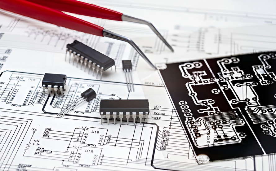
This is why the component list drives the fabrication choice. Encoder interfaces are sensitive to noise, the power stage dissipates heat close to the encoder, and the communication interface has timing requirements that a long, poorly referenced trace will not meet. Design starts from the mechanical envelope and works back toward layer count and material, rather than the other way around.
Why HDI Appears Inside a Joint
High density interconnect is normally associated with phones and wearables, but the pressure that makes it useful is the same here: many nets in a small area. A joint controller connects an encoder, a gate driver, current sensing, a communication transceiver and a processor, and the routing between them cannot spread out because the enclosure is circular and the connector positions are fixed.
Microvias and finer lines allow that routing to be completed without adding layers that would make the assembly thicker. The trade is process complexity, since laser drilled microvias and plated filled vias have their own yield characteristics, and stack ups with several build up layers need tighter registration control. Factories that build this class of work therefore treat HDI capability as a process discipline rather than a layer count claim.
Flex and Rigid-Flex for Continuous Motion
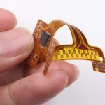
A joint that moves all day cannot rely on a cable harness. Flexible circuits and rigid-flex constructions replace connectors and wires with laminated conductors, which reduces mass, removes a common failure point and makes assembly repeatable. In a humanoid arm the flex section usually crosses the rotation axis, so it experiences bending in service rather than during installation only.
Designing for that means controlling bend radius, orienting conductors so they are not loaded across their width, opening the coverlay correctly in the bend region and adding stiffeners where the flex meets the rigid section. These rules are well known in consumer electronics and equally applicable here, but they have to be applied from the first layout. A mechanical failure in a flex tail is not repairable in the field, and it also damages the reputation of the module supplier. Programs that involve a manufacturer experienced in flexible circuit assembly early discover the constraints before the tooling is cut.
Driving a Motor Beside a Sensitive Encoder
The power stage and the encoder share a small volume, which creates the central electrical conflict of joint electronics: high current switching next to microvolt level position feedback. Copper weight and via plating have to carry continuous current without unacceptable temperature rise, while the encoder signal path needs a clean reference and physical separation from switching nodes.
Layout addresses this through controlled return paths, separate ground regions joined at defined points, and generous copper for thermal spreading rather than only for current. Thermal vias under the drive devices help move heat into the housing, and the choice of copper thickness is a compromise between heat, weight and the fine line capability needed elsewhere on the same board. In practice most joints end up with a thick copper power region and a fine line control region on the same stack up, which is a fabrication challenge before it is a circuit design one.
Precision Stages Raise the Signal Integrity Bar
Motion stages used in optical module fibre coupling and wafer inspection reach positioning accuracy measured in nanometres by combining a mechanical design with a control loop that reacts in microseconds. The servo driver reported by the same supplier uses an FPGA architecture with one hundred kilohertz pulse width modulation and a five kilohertz current loop bandwidth, and the platform synchronises over EtherCAT with a one millisecond refresh period and jitter controlled to about one hundred nanoseconds.
Nanometre positioning does not require nanometre fabrication, but it does remove the error budget that used to absorb electrical noise. A fluctuation on the current feedback path, a shift in encoder timing or an unstable supply rail appears as position error at the output. That is why impedance control, power integrity and grounding stop being abstract quality attributes and become the practical limits on achievable accuracy.
Real-Time Control Platforms Concentrate Interfaces
The control platform released alongside the joint modules connects upward to AI models and downward to joints, drives, vision, force and tactile sensing, with hardware support for a two kilohertz control cycle and a high speed fieldbus. Interfaces multiply, and each one brings its own signalling requirement onto the same board.
The consequence is a board that mixes high speed differential pairs, isolated industrial interfaces, analogue sensing and power conversion. High layer count and HDI solve the space problem, but the electrical problem is solved by stack up design: continuous reference planes for the high speed links, separation between switching and sensing regions, and impedance targets that are specified and then actually measured. Boards like this are usually validated with functional testing after assembly rather than by inspection, because the failure modes appear only when the interfaces run at rate.
Consistency Across Thousands of Units
A single controller that holds its control cycle is an engineering demonstration. Thousands of controllers that all hold the same control cycle is a product. The difference is process consistency: the same impedance on every board, the same barrel copper in every via, the same solder joint quality under the same thermal load.
Robot programmes scale faster than most industrial products, and a supplier that validated a design on twenty boards may be asked for twenty thousand within a year. Managing that transition requires statistical process data, controlled changes and a clear record of what was altered and when. It is unglamorous work, but it is what separates a supplier that can support a robot programme from one that can only prototype for it.
Coordinating Three Board Types in One Product
A humanoid robot contains control boards, power boards and flexible interconnect boards, and each of those follows a different process route. Control boards need fine lines and high layer counts, power boards need heavy copper and thermal management, flex boards need thin materials and mechanical design support.
Splitting them across three suppliers creates interface problems that land on the robot manufacturer: tolerance stack up between modules, conflicting qualification schedules and slow engineering change. Keeping them under one manufacturing chain, from board fabrication through assembly, shortens the loop when a design change is needed and keeps process data comparable across the three types. For a product that is still iterating quickly, that coordination is worth more than a marginal price difference.
Testing an Assembly That Moves
Electrical test alone does not qualify a joint controller. The assembly has to be exercised through its motion range while instrumented, because intermittent faults caused by a flex section or a marginal solder joint often appear only when the mechanism moves. In-circuit and functional testing catches assembly defects, while a motion test catches the mechanical ones.
The practical sequence is to test the bare board for continuity and impedance where specified, test the assembled board functionally, then run the module through its thermal and motion envelope before release. Suppliers who build both the board and the assembly can carry that sequence without shipping units between sites, which shortens the loop when a failure is found and keeps the failure analysis attached to the correct process step.
What This Means for Robot Programmes
The demand signal from humanoid robots and precision motion equipment is real, but it is different from ordinary industrial electronics. Volumes rise quickly, technical requirements are stringent, and the product continues to change while it ships. Suppliers who succeed in this market are the ones that can absorb change without losing process control, and that can document what they did when a customer asks why a batch behaved differently.
For design teams the practical advice is to involve the board manufacturer while the enclosure is still being defined, to keep the stack up able to accommodate both power and fine line routing, and to treat flex sections as mechanical components with fatigue life rather than as wiring. Those decisions cost little at the beginning and are expensive to reverse once a joint module is in volume production.