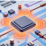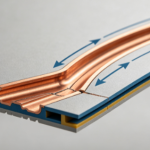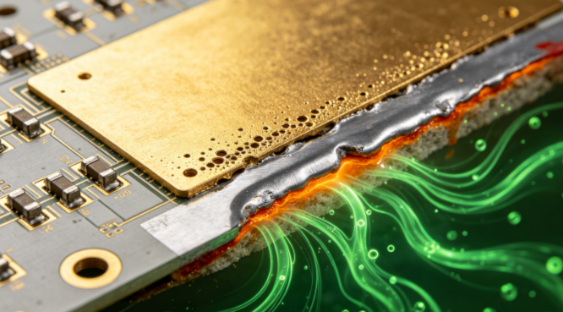
A darkened gold surface, poor solderability, or weakened BGA solder joints does not always indicate oxidation of the gold layer. In some ENIG failures, the underlying nickel-phosphorus layer is the actual region where corrosion initiates.
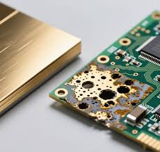
During failure analysis, localized corrosion may appear as pits, voids, discoloration, or interfacial separation beneath the gold surface. If elements such as chlorine or sulfur are detected near the affected interface, the investigation should consider flux residue, ionic contamination, moisture, and the electrochemical stability of the nickel layer.
This type of failure is important because the immersion-gold layer is extremely thin compared with the electroless nickel layer. The nickel layer provides much of the mechanical and diffusion-barrier function of the ENIG structure. Damage to the nickel layer can therefore affect both surface finish integrity and solder joint reliability.
What Is ENIG and Why Is the Nickel Layer Important?
Electroless nickel immersion gold (ENIG) typically consists of an electroless Ni-P layer covered by a thin immersion-gold layer.
The nickel layer is not pure nickel. It is an electroless nickel alloy containing phosphorus, with the actual phosphorus content depending on the plating chemistry and process.
The gold layer primarily protects the nickel surface and provides a suitable soldering interface. Because the immersion-gold layer is relatively thin, it should not be considered a thick corrosion barrier comparable to conventional electroplated gold.
The functional structure can therefore be simplified as:
Copper substrate → Ni-P layer → immersion gold → solder
If the Ni-P layer becomes locally porous, excessively stressed, contaminated, or chemically attacked, the integrity of the entire surface-finish system can be compromised.
How Nickel Corrosion Occurs
Nickel corrosion is fundamentally an electrochemical process rather than a single chemical reaction.
In the presence of moisture and an electrolyte, nickel can undergo an anodic oxidation reaction:
Ni → Ni²⁺ + 2e⁻
The released electrons participate in a corresponding cathodic reaction. Depending on the environment, oxygen reduction or hydrogen evolution may occur.
For example, under acidic conditions, hydrogen-ion reduction can be represented as:
2H⁺ + 2e⁻ → H₂
The overall corrosion rate depends on the electrochemical environment, including pH, moisture, temperature, dissolved oxygen, ionic contamination, surface condition, and local galvanic effects.
This is why it is not technically accurate to attribute ENIG nickel corrosion to one universal reaction equation.
Why Chloride Ions Can Accelerate Localized Corrosion
Chloride ions are particularly important in localized corrosion because they can participate in the breakdown of passive surface conditions and promote metal-ion transport.
When chloride-containing contamination remains on or near the PCB surface, moisture can dissolve the ionic residues and create a localized electrolyte.
The resulting environment can increase the susceptibility of exposed or defective nickel regions to electrochemical attack.
A simplified process is:
Moisture + ionic contamination → localized electrolyte → nickel dissolution → Ni²⁺ formation → localized corrosion
The actual mechanism can be more complicated because organic acids, activators, flux residues, oxygen, sulfur-containing compounds, and other contaminants may participate simultaneously.
Therefore, detecting chlorine by EDS near a corroded interface is useful evidence, but it does not by itself prove that chloride was the sole cause.
The Role of Flux Residue
Flux residue can become a significant reliability concern when it contains ionic or potentially corrosive species and remains trapped around fine-pitch components or PCB surface features.
During solder reflow, most properly formulated flux systems undergo chemical changes designed to facilitate oxide removal and solder wetting. However, the amount and composition of remaining residue depend on the flux chemistry, application quantity, reflow profile, cleaning process, and PCB surface condition.
After reflow, residual contamination can become more problematic when combined with:
- High humidity
- Ionic contamination
- Elevated temperature
- Inadequate cleaning
- Fine-pitch structures
- Surface-finish defects
- Long-term electrical bias
In a humid environment, ionic residues can form a conductive electrolyte. This may contribute not only to nickel corrosion but also to electrochemical migration and insulation-resistance degradation.
Why Corrosion Can Appear as Localized Pitting
A common characteristic of surface-finish corrosion is that it does not necessarily progress uniformly across the entire pad.
Local differences in:
- Gold coverage
- Nickel microstructure
- Phosphorus distribution
- Surface roughness
- Plating thickness
- Residual stress
- Contamination
- Moisture retention
can create microscopic electrochemical cells.
As a result, corrosion may develop preferentially at specific locations.
This can produce a pitting or porous appearance rather than simple uniform thinning.
Once a localized defect exposes or weakens the Ni-P layer, continued environmental exposure may enlarge the affected region.
Nickel Thickness Must Be Evaluated With the Complete ENIG Structure
It is tempting to conclude that thicker nickel automatically means better corrosion resistance.
In practice, nickel-phosphorus layer performance depends on more than nominal thickness.
Important factors include:
- Nickel thickness
- Phosphorus content
- Plating chemistry
- Bath condition
- Deposition rate
- Surface activation
- Copper surface preparation
- Plating uniformity
- Internal stress
- Gold coverage
- Post-plating handling
An excessively thin layer may provide insufficient barrier thickness or mechanical margin.
However, simply increasing thickness does not automatically eliminate corrosion. Poor plating chemistry or excessive internal stress can still create reliability problems.
Therefore, the correct engineering approach is to establish a qualified process window rather than define one universal nickel thickness as suitable for every PCB.
Surface Preparation Directly Affects Nickel Adhesion
Before electroless nickel deposition, copper surfaces normally undergo controlled cleaning and activation steps.
The objective is to provide a chemically active and sufficiently clean surface for uniform nickel deposition.
If the pretreatment is inadequate, potential defects may include:
- Poor nickel adhesion
- Nonuniform deposition
- Local voids
- Interfacial contamination
- Increased susceptibility to corrosion
- Interfacial separation during soldering
This is why ENIG process control should cover the entire sequence rather than focusing only on the final gold thickness.
Moisture Can Turn Contamination Into an Electrochemical Problem
Dry ionic contamination may have limited immediate effect.
The situation changes when moisture is present.
A simplified reliability chain is:
Ionic contamination + moisture → conductive electrolyte → electrochemical reaction → localized corrosion
Temperature can further accelerate chemical and electrochemical processes.
Repeated humidity and temperature exposure can therefore reveal weaknesses that are not visible immediately after PCB fabrication.
For products operating in high-humidity environments, engineers should consider humidity exposure, ionic cleanliness, conformal protection where applicable, and the long-term stability of the surface finish.
How ENIG Corrosion Can Affect Solder Joint Reliability
The relationship between surface-finish corrosion and solder joint reliability is not limited to appearance.
A damaged nickel surface may affect:
- Solder wetting
- Intermetallic formation
- Solder adhesion
- Interface strength
- Pad integrity
- Contact resistance
- Mechanical durability
If corrosion develops at the nickel/gold interface or nickel/copper interface, the resulting weakness can become more serious during thermal cycling or mechanical loading.
For BGA packages, the problem may be difficult to identify visually because many solder joints are hidden beneath the component.
Consequently, a failure-analysis program may require:
- X-ray inspection
- Cross-section analysis
- SEM examination
- EDS elemental analysis
- Surface-finish thickness measurement
- Ionic contamination testing
- Solderability testing
- Mechanical or thermal reliability testing
The results should be correlated rather than relying on a single analytical technique.
Why EDS Results Need Careful Interpretation
EDS can detect elements associated with contamination or corrosion products, including chlorine and sulfur.
However, EDS results should be interpreted together with morphology and location.
For example, detecting Cl near a damaged area does not automatically demonstrate a specific chloride corrosion mechanism. Chlorine may originate from processing chemicals, handling contamination, flux residues, cleaning materials, or other sources.
A stronger failure-analysis conclusion should establish:
Where the element is located → what chemical form may be present → what corrosion morphology exists → whether the process history supports the proposed mechanism.
Cross-sectional SEM/EDS, surface analysis, ion chromatography, and process-history review can provide complementary evidence.
Thermal Aging and Storage Conditions
Post-plating aging and storage conditions can influence ENIG performance, but there is no universal thermal-aging recipe that guarantees corrosion resistance for every ENIG system.
Engineers should instead verify the manufacturer’s qualified process conditions and applicable reliability requirements.
Important storage controls include:
- Temperature
- Relative humidity
- Packaging integrity
- Desiccant condition
- Exposure time
- Surface contamination
- Reflow history
For moisture-sensitive assemblies, the PCB storage and pre-assembly handling process should also be coordinated with the component and assembly requirements.
High-Frequency and Special-Material PCBs Require Separate Validation
The corrosion mechanism described here should not be applied indiscriminately to every PCB material system.
High-frequency laminates, PTFE-based materials, low-loss resin systems, metal-core PCBs, and hybrid constructions can have different moisture behavior, thermal properties, surface treatments, and manufacturing processes.
The surface finish itself should therefore be evaluated independently from the dielectric material.
In other words, changing from conventional FR-4 to a high-frequency laminate does not automatically eliminate ENIG corrosion risk.
The appropriate qualification method should consider the complete material and manufacturing stack.
Three Key Engineering Checks for ENIG Quality
A practical ENIG corrosion control strategy can focus on three areas.
1. Check the Surface-Finish Process
Verify:
- Copper cleaning
- Micro-etch control
- Activation
- Electroless nickel deposition
- Nickel thickness
- Phosphorus content
- Immersion-gold deposition
- Bath chemistry
- Process uniformity
2. Control Ionic Contamination
Monitor potential sources of contamination from:
- Flux
- Cleaning chemicals
- Plating chemicals
- Handling
- Water quality
- Manufacturing environment
Where reliability requirements are stringent, ionic contamination testing can provide more meaningful information than visual inspection alone.
3. Verify Reliability Under the Actual Application Conditions
Testing should reflect the product’s actual environment.
Depending on the application, this may include:
- Temperature cycling
- Damp heat
- High-temperature exposure
- Solderability testing
- BGA joint reliability testing
- Surface-finish adhesion evaluation
Test conditions should be based on the applicable product specification and qualification standard rather than one universal temperature, humidity, or cycle count.
What to Do When ENIG Corrosion Is Suspected
When darkened gold, solderability degradation, or pad separation is observed, the PCB should not be treated simply by polishing or chemically stripping the surface.
A structured failure-analysis process is safer and more informative:
- Preserve representative failed and good samples.
- Record storage, assembly, and reflow history.
- Inspect the surface under optical microscopy.
- Measure the ENIG layer structure.
- Perform cross-section analysis.
- Use SEM/EDS to characterize corrosion morphology and elemental distribution.
- Check ionic contamination where appropriate.
- Review the plating process and bath-control records.
- Compare affected areas with normal production areas.
- Confirm the failure mechanism through controlled testing.
Strong chemical treatments involving acids or fluoride-containing reagents should only be performed by qualified personnel under an approved laboratory procedure. They should not be used as an improvised production-line method for “restoring” a damaged ENIG pad.
How Kingda Can Help Control ENIG Reliability
At Kingda, ENIG reliability can be managed through coordinated control of surface preparation, electroless nickel deposition, immersion gold, cleanliness, storage, assembly compatibility, and reliability validation.
For demanding applications, the objective is not simply to achieve a specified gold thickness. The complete surface finish must maintain its chemical stability, adhesion, solderability, and mechanical integrity throughout manufacturing and service.
The key principle is:
When an ENIG surface becomes dark or a solder joint loses strength, do not assume that the gold has oxidized. Investigate the Ni-P layer, ionic contamination, moisture exposure, plating quality, and the complete electrochemical environment.
A combination of process control and evidence-based failure analysis is the most reliable way to distinguish true nickel corrosion from soldering defects, contamination, oxidation, or other ENIG-related failure mechanisms.