FR-4 Material in PCB Construction and Its Applications
Almost every rigid board in production is built on the same family of material, and understanding what that material is explains a great deal about the limits of the board: why it is stiff, why it is dimensionally stable in one direction and less so in another, why it resists burning, and why some applications need something else entirely.
What FR-4 Means
FR-4 material is a grade rather than a single substance. The letters indicate a flame retardant specification, and the number distinguishes this material from others in the same class. In practice the term describes a glass fiber reinforced epoxy laminate: a woven glass cloth that provides mechanical structure, impregnated with an epoxy resin that has been formulated so that it will not sustain combustion. The specification means that a sample of the material must extinguish itself after the flame is removed, which is a requirement in most electronic equipment and the reason the grade became the default for rigid boards.
What a PCB Is Made Of
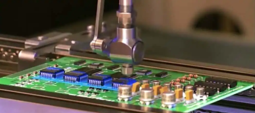
A printed circuit board is built from a small number of layers, each of which has a function. The base material is the foundation and gives the board its rigidity. Copper is added to one or both functional surfaces as a thin conductive foil, and it becomes the traces and planes after etching. The solder mask covers the copper, protects it from oxidation and from accidental contact with conductive material that could cause a short, and defines the openings where solder is applied to attach components. Silkscreen is applied last and carries the reference designators and symbols that identify each component. The choice of base material is what distinguishes one class of board from another: high frequency laminates, metal core boards on aluminum, iron or copper, and ordinary double-sided and multilayer constructions are all defined by what the base is made from.
Why the Material Becomes the Traces
The copper foil originally covers the entire surface of the panel. During fabrication, the unwanted areas are etched away, and what remains is the network of conductors. Ground and power planes are formed in the same operation, as large areas of copper rather than as traces, which is why a board can carry both dense routing and a low-impedance return path on the same layer. The base material underneath is an electrical insulator that resists bending, and this combination of an insulating substrate with etched copper on its surface is what makes high density, low weight and small volume possible in modern equipment.
Why FR-4 Performs as It Does
The glass fiber cloth is what gives the laminate its structural stability, and the resin chemistry is what gives it durability and mechanical strength. The combination produces a material that is dimensionally predictable, flat, smooth, free of pits and held to a defined thickness tolerance, which is what allows it to be used for high performance electrical insulation as well as for circuit boards. Those same properties explain its wider use, which extends well beyond electronics: stiffeners for flexible circuits, backing boards for drilling, insulating spacers, transformer insulation, motor insulation components, precision test fixtures and machined insulating parts all rely on the same material. Where a board is used as a mechanical component rather than only as an electrical one, the relevant properties are described in this article on board outline and mounting design.
Where FR-4 Boards Are Used
Single-sided, double-sided and multilayer boards in FR-4 are used across military, communications, computer, digital, industrial instrumentation and automotive electronics. The material satisfies the requirements of ordinary industrial products and offers a good balance between cost and performance, which is why it remains the default even where other materials are available. The limits appear when the requirement moves outside that range. A design that must operate at high frequency needs a laminate with a lower dielectric constant and lower loss. A design that must remove a large amount of heat from a small area may need a metal core. A design that must flex needs a polyimide film rather than a rigid glass laminate. In each case the base material, not the layout, is the limiting factor.

Reading a Material Specification
A laminate specification is more than a single grade name. It includes the glass transition temperature, which determines how the material behaves at soldering temperature; the dielectric constant and loss tangent, which determine high frequency behaviour; the coefficient of thermal expansion, which determines how the material moves during thermal cycling; the moisture absorption, which affects dimensional stability and the risk of delamination; and the thickness tolerance, which determines whether an impedance target can be held. A board that must survive repeated thermal excursions, such as a thick multilayer assembly soldered at high temperature, will need a material chosen against those numbers rather than against the generic grade. The way the material behaves dimensionally during processing is described in this article on PCB dimensional stability, and the stackup decisions that follow from it are covered in this article on layer stackup from one to eight layers.
Practical Example
A typical industrial battery control board illustrates how ordinary the choice usually is: FR-4 base material, two layers, 1.6 mm finished thickness, an outline of roughly 80 mm by 300 mm, and a solder mask with white silkscreen. Nothing in that description is unusual, and that is the point. FR-4 remains the default because it is adequate for the large majority of products, and the engineering effort is better spent on the layout and the stackup than on searching for a more exotic material that the design does not need.
Thickness, Copper Weight and Panel Formats
Three numbers describe a laminate order before any routing decision is made: the finished board thickness, the copper weight on each side, and the panel format the shop will use. Common finished thicknesses are 0.8 mm, 1.0 mm, 1.6 mm and 2.0 mm, and the choice is usually driven by mechanical requirements rather than electrical ones, since a thicker board resists bending and supports heavy connectors better while a thinner one is easier to fit into a slim enclosure. Copper weight follows from the current the board must carry and from the impedance the design requires, with one ounce being the default and heavier foils ordered where the current demands it. The panel format matters because it decides how many boards fit on one panel and therefore how much material is consumed per unit; an outline that nests efficiently reduces cost with no change to the circuit. For a multilayer board the stackup adds further decisions about which layers carry copper and how thick each dielectric must be to hit an impedance target. All of these choices should be recorded on a stackup drawing that travels with the fabrication data, because a shop that has to infer them from the copper artwork will make reasonable assumptions that may not match the design intent.
FAQ
Is FR-4 a material or a specification? It is a grade of glass fiber reinforced epoxy laminate. As an FR-4 material it refers to a flame retardant class, and the material behind it is a woven glass cloth in an epoxy resin.
What are the four layers of a simple PCB? Base material, copper, solder mask and silkscreen. The copper forms the traces and planes, and the mask and silkscreen protect the copper and identify the components.
When should a different base material be used? When the requirement falls outside what FR-4 can do: high frequency operation, high heat density, or a need for flexibility.