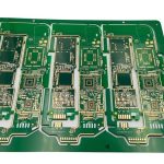
High-Speed Backplane PCB Design: A Stage-by-Stage Process
A backplane is the board everything else plugs into, and it is designed differently from any other board in the system. Its interfaces are defined by the modules it has to connect rather than by its own function, its mechanical envelope is set by the chassis, its layer count is driven by the number of high-speed channels that must cross it, and its failure takes the entire system down. That combination means the design process is longer and more front-loaded than a typical card design, and most of the risk is retired before a single trace is routed.
Why the Process Differs
On a normal board the design starts with a schematic. On a high-speed backplane the schematic is almost the last artifact, because the connections are defined by a pinmap negotiated between all the modules. The backplane is, in effect, the physical embodiment of a system architecture: slot count, channel count, power distribution, cooling airflow, and mechanical guidance all land on the same piece of laminate.
Stage One: Technical Feasibility
The first stage proves that the target data rate can actually cross the system. That means three evaluations, and all of them should be measured rather than assumed.
The first is the serializer-deserializer selection and its drive capability. Simulation gives an indication, but a vendor demonstration board gives a measurement, and a measurement is worth much more when the channel is long.
The second is connector selection. A backplane connector is not a passive mechanical part; its impedance profile, its crosstalk between adjacent wafers, and its loss at the operating frequency set the ceiling for the whole channel. The practical way to evaluate candidates is a dedicated connector test board that lets insertion loss, return loss, and crosstalk be measured on the actual footprint.
The third is laminate selection. Loss in the channel is the sum of the loss in the daughter cards, the connector, and the backplane itself, and the backplane is usually the longest segment. Choosing a low-loss laminate with a known dielectric constant and loss tangent is what makes the channel budget achievable, and it has to be decided before the stackup is fixed.

Stage Two: Hardware Architecture
With the channel feasible, the architecture is settled. How many service cards does the system need, and how much bandwidth per slot? How many switch cards, control cards, power modules, and fans? Each of those answers sets a slot count and a connector type.
The mechanical side of this stage is not a detail to be inherited from the chassis drawing. Slot pitch affects routing room between connectors, card guidance determines the keep-out around each slot, overall power sets the bus bar or heavy copper requirements, and airflow design determines where components and their keep-outs can sit. A backplane that ignores cooling in its layout will be redesigned.
Stage Three: Overall Design and Pre-Simulation
The architecture and feasibility work is written into a design document, and the high-speed channel topology is simulated before layout begins. Pre-simulation is where the stackup, the trace geometry, and the via structure are chosen, and it is much cheaper to iterate there than in copper.
Stage Four: The Pinmap
This is the stage that decides whether the board is manufacturable. Every module interface has to be assigned to specific connector pins, and two constraints pull against each other.
The first is crosstalk control. Whether adjacent high-speed pairs are separated by one ground pin or two, and how differential pairs are arranged across a wafer, determines the isolation between channels. The assignment has to be made deliberately rather than left to the order in which signals were listed.
The second is routability. A backplane with a large slot count carries a very large number of nets, and the layer count needed to route them depends directly on how the nets are distributed across pins and connectors. A pinmap that scatters signals across connectors can double the layer count compared with one that groups them by channel. Since backplanes are already among the highest layer-count boards in common use, that decision has a direct and large effect on cost.
Once the pinmap is agreed, the schematic is largely a mechanical translation of it, and the high-frequency trace and data bus routing rules govern how the connections are then realised.
Stage Five: Layout
If the earlier stages were done properly, layout is mostly execution: follow the routing rules, keep the pair-to-pair spacing, control the reference plane transitions, and route the channels in a consistent order. Two things still deserve attention.
The first is power delivery. Backplanes carry the full system current, often at low voltage and high amperage, and the copper has to be sized for it with a temperature-rise allowance rather than by habit. Connector pin assignments for power and return, plane segmentation, and the placement of bulk capacitance all belong to this stage. Trace and plane widths should be calculated from the trace width and current capacity relationship, not estimated.
The second is the stackup. A high-speed backplane is a thick board with many layers, and the layer arrangement has to keep the high-speed references continuous while also providing enough power planes. The principles in the layer stackup guide scale up to these counts, but the constraint is tighter, because a via that changes reference planes on a thick board creates a long stub that has to be addressed with back-drilling or blind vias.

Stage Six: Unit Test
Backplane unit test focuses on the signal integrity of the high-speed channels rather than on simple continuity. Insertion loss, return loss, and crosstalk are measured on representative channels, sometimes using a connector test board as a reference. This stage is what confirms that the pre-simulation, the stackup, and the fabrication tolerance all landed where they were intended.
Stage Seven: System Integration
System integration takes longer on a backplane than on almost any other board, because every module combination is a test case. A service card has to be checked against the switch card, the control card against the service cards, and the management module against the whole chassis. Add environmental testing, thermal cycling, and reliability work, and the integration phase becomes a program in its own right. The backplane designer stays involved throughout, because the failures that appear at this stage are usually channel or power delivery issues rather than assembly defects.
FAQ
Why is the pinmap so important? It sets both the crosstalk between high-speed channels and the number of routing layers needed to escape every connector. A poor assignment can double the layer count, and layer count is the largest cost driver on a board this size.
Can a backplane be designed from simulation alone? Not safely. Simulation is necessary for the stackup and geometry, but connector behaviour and channel loss are best confirmed on a test board before the design is frozen.
What drives the layer count? The number of nets crossing the board, the pinmap arrangement, the crosstalk spacing rules, and the number of power and ground planes the current requires.
Where do the failures usually appear? In system integration rather than in unit test, because that is where the combination of modules, power load, and thermal conditions actually occurs.