High Temperature PCB: Materials, Design and Applications
Most boards spend their life near room temperature, and the design rules that follow from that assumption are built into every laminate datasheet. Move the operating temperature up and those assumptions weaken one by one: the laminate softens, expansion increases, solder joints see more stress and component derating becomes the limiting factor.
What Makes a Design High Temperature
The threshold is not a single number. A product that runs at 105 °C in a sealed enclosure, a board that must survive a lead-free reflow profile and a device mounted beside a power stage all create high-temperature requirements, and each is solved differently.
The practical question is the maximum temperature the board will reach, for how long, and how many times. A brief excursion during assembly is a different problem from a continuous operating temperature, and the material selection follows from that distinction.
High Tg Laminates
The glass transition temperature is the point at which the resin softens. Above it, the laminate expands more rapidly in the z-axis and its mechanical properties degrade, which is what stresses plated barrels during reflow.
Standard FR-4 sits around 130 to 140 °C, mid-range materials around 150 to 170 °C and high Tg grades above 170 °C. A high Tg laminate is the first answer to almost every high-temperature requirement because it is compatible with standard processing and adds cost without changing the fabrication route.

Polyimide and Other High Temperature Materials
Polyimide laminates maintain their properties to considerably higher temperatures and remain the standard choice for aerospace and severe industrial applications. They are more expensive, more difficult to process and more hygroscopic, requiring baking before assembly to avoid delamination.
Beyond polyimide, the options become specialised: ceramic substrates for the highest temperatures and thermal loads, metal core boards where heat spreading is the priority, and BT epoxy for applications that need moderate thermal improvement with better dimensional stability than standard FR-4.
Thermal Expansion and Via Reliability
Z-axis expansion is the mechanism that destroys high-temperature boards. The laminate expands more than the copper barrel, so the barrel is stretched during every thermal excursion, and a thin or brittle deposit eventually cracks.
The mitigations are cumulative rather than alternative: a higher Tg material reduces the expansion rate, a thicker and more ductile plating resists the strain, and a design that avoids the smallest via size keeps the aspect ratio within a range the process can plate reliably. Where the product also sees thermal cycling in service, the same factors determine the number of cycles the barrel survives.
Component Derating and Selection
Above a certain temperature, the board is no longer the limiting component. Electrolytic capacitors lose life rapidly with temperature, semiconductors have a maximum junction temperature that must be respected, and resistors have a power rating that is specified at a reference ambient.
Derating applies a margin below the rated limit: a capacitor operated at a fraction of its rated voltage, a resistor at a fraction of its power rating, and a semiconductor at a reduced junction temperature. The appropriate factor depends on the reliability target, and applying it systematically is what distinguishes a high-temperature design from one that merely uses a better laminate.
Layout for High Temperature Operation
Placement determines the temperature each component experiences. Power devices should be spaced apart so that their heat does not accumulate, and temperature-sensitive components such as crystals, references and electrolytic capacitors should be placed as far from them as the layout allows.
Copper is the primary heat spreader, so pours and planes under and around power devices are a design feature rather than a routing convenience. Thermal vias connect those areas to internal planes, and the copper area connected to each via should be sized for the power being dissipated rather than for the available space.
Soldering and Assembly Limits
Assembly imposes the highest temperature the board will ever experience. Lead-free reflow peaks well above 240 °C, and the board spends a significant time above its glass transition temperature during that excursion.
That is why high Tg materials are required even for products that operate at moderate temperatures. The requirement is not the operating temperature but the assembly profile, and a design that ignores it will pass functional test and fail on the first reflow or shortly afterwards.
Applications That Demand High Temperature Boards
Automotive under-hood electronics, industrial motor drives, downhole instrumentation, aerospace systems and power conversion equipment are the familiar applications. Each combines a high ambient temperature with a reliability expectation that rules out marginal designs.
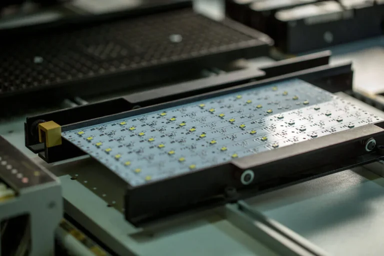
LED lighting sits in a different category: the ambient is moderate but the local temperature under the emitters is high, so the laminate is chosen for its thermal performance as much as its Tg. A metal core substrate may be the answer there rather than a higher grade of FR-4, and the correct choice follows the thermal calculation, as described in trace width and current calculation for the conductors involved.
Verifying a High Temperature Design
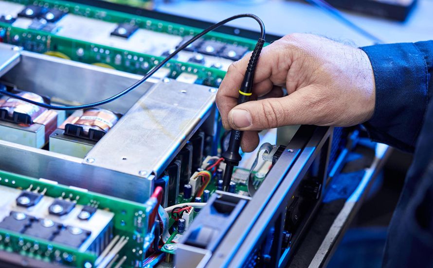
Verification combines analysis with test. Thermal simulation estimates the temperature of each component under worst-case load, and thermal cycling validates the plated barrels and the solder joints.
The board itself should be inspected after cycling: microsections of vias from a coupon, and examination of the laminate for delamination or measling. Where the design uses a high-temperature laminate, reviewing the fabrication assumptions in design and fabrication before release confirms that the chosen material is one the supplier processes routinely rather than occasionally.
Comparing High Temperature Substrate Options
Four material families cover most requirements, and the choice follows the operating temperature rather than the assembly profile. Standard FR-4 handles products that run warm but assemble with lead-free reflow, provided the excursions are brief and the via design is conservative. A high Tg laminate adds margin for both assembly and operation at modest cost.
Polyimide takes the operating temperature considerably higher and is the standard choice when the equipment is expected to function in a hot environment rather than merely survive assembly. It requires baking before soldering and more careful handling, which is a process cost rather than a design constraint.
Metal core boards address local heat rather than ambient temperature, and ceramic substrates address both at the highest cost. Selecting between them on the basis of the junction temperature calculation, rather than on the basis of the ambient alone, is what keeps the cost proportionate to the requirement.
Documenting the Thermal Requirement
The thermal requirement belongs on the fabrication drawing rather than in a conversation. State the operating temperature, the assembly profile and the material class, so that the fabricator can select a construction that meets all three rather than the one they were told about.
Where the design uses a high Tg laminate together with a controlled-impedance stackup, the two requirements interact: a thicker dielectric for impedance may require a different prepreg schedule, which changes the achievable Tg. Reviewing multilayer prototype requirements alongside the thermal specification keeps those decisions consistent.
FAQ
Is a high Tg laminate enough for a high temperature product? It addresses the laminate side, but component derating, thermal spreading and the solder joint design all have to be addressed as well. Material choice is the first step rather than the whole solution.
When is polyimide justified? When the operating temperature or the thermal cycling requirement exceeds what a high Tg epoxy can sustain. Polyimide costs more and is harder to process, so it is chosen for the requirement rather than by preference.
Why do boards fail after reflow if they operate cool? Because assembly is the highest temperature the board experiences. The excursion is brief but it is enough to stress a barrel that was marginal, and the failure appears later as an intermittent open circuit.