Humanoid Robot PCB Demand: What Mass Production Changes
When a humanoid robot program moves from a few hundred units to ten thousand, the electronics inside it stop behaving like a research project. Orders in that range were reported for consumer humanoid platforms during 2026, with the first deliveries scheduled for September. The shift matters because a humanoid robot PCB must then survive a manufacturing system rather than a laboratory bench.
A full size unit carries several electronic systems at once. Main compute, motor drives, encoders, vision, torque sensing, power management and communication each map to a different board class. Some are dense HDI designs, some are heavy copper power boards, and the moving joints need flexible or rigid flex interconnect. One robot therefore generates dozens of part numbers before shipping begins.
Why Prototype Logic Breaks at Ten Thousand Units
During development, engineers expect to change the board. A stack up is revised, a via is moved, a connector is swapped, and the supplier delivers a new build within days. That rhythm works when the quantity is small and the cost of a revision is measured in engineering hours rather than production line downtime.
At ten thousand units the same freedom disappears. Every board type enters production at roughly the same time, so a single unstable process can stall the whole assembly schedule. Companies that succeed at this stage are usually the ones that freeze designs earlier than they would like and then invest the saved time in process capability instead.
Main Compute Boards Resemble High Performance Computing
The compute module has to fuse vision, speech, motion control and sensor data in real time, which pushes processors, memory and high speed interface devices into a small area. Ball grid array counts rise, escape routing becomes tight, and ordinary through holes stop being sufficient for fan out. HDI with microvias becomes the practical answer.
That changes what the factory must control. Laser drilling, via filling, layer to layer registration and fine line etching all become yield sensitive. The available HDI and high layer count capability decides whether a design can be produced at a stable rate, not only whether a first article can be built.
Signal Integrity Arrives With the Density
Once the compute board carries camera links, memory buses and high speed serial interfaces, the stack up stops being a mechanical drawing. Impedance targets, reference plane continuity and return path planning determine whether the module passes electromagnetic compatibility testing on the first attempt or the fourth, and that difference is expensive at volume.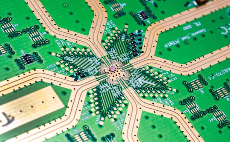
Suppliers therefore need to review the stack up with the customer rather than accept a Gerber package without comment. Small adjustments to dielectric thickness or copper weight can solve a signal problem without adding layers, but only when the question is raised before lamination instead of after final test.
Power Boards Inside Every Joint
Each actuator has its own driver electronics, and those boards carry real current. Copper thickness, barrel plating, thermal path design and the layout around the power stage matter more than fine geometry. The same board usually also handles encoder feedback and control signals, so noise separation becomes a layout discipline as much as a circuit design task.
Heat is the quiet constraint. Motors draw current in bursts, so the thermal design must handle peaks rather than averages. Designers who treat the copper plane as a heat spreader, and who specify via arrays beneath the switching devices, often find that the drive board runs cooler without changing a single component.
Flex and Rigid Flex in Narrow Spaces
Shoulders, elbows, wrists and knees have very little room, and a harness that works in a prototype quickly becomes the heaviest and least reliable part of the assembly. Flexible circuits solve the space problem, and rigid flex solves the connector problem by turning a cable assembly into one continuous structure with soldered terminations at both ends.
Volume manufacturing then shifts attention to how the flexible sections are built. Coverlay construction, stiffener placement and the relationship between conductor direction and bend axis decide the service life of the part. A supplier with real flex and rigid flex assembly experience will raise these points during design review.
Bend Life Becomes a Manufacturing Specification
In a laboratory, a flexible circuit that fails once in a thousand cycles can be replaced by hand. Across tens of thousands of joint modules, the same defect rate becomes a field failure pattern. Bend life therefore moves from a design note into a manufacturing specification with a defined test method and a defined sample size for every lot.
Adhesiveless laminate, rolled annealed copper and careful control of the neutral axis all help. So does honest reporting. A supplier that measures bend life on production lots, rather than quoting a figure from a material datasheet, gives the customer something that can actually be planned around.
The Yield Question Nobody Escapes
Microvia plating defects, voids beneath a ball grid array, impedance drift and damage in a bending zone are all survivable in small quantities. Scaled to a ten thousand unit program they convert directly into cost, schedule pressure and reputation. Yield is the variable that decides whether a robot program ships on time.
This is where process control stops being paperwork. Statistical acceptance at each stage, traceability from panel to final assembly and a defined disposition for out of specification material are what allow a customer to plan a production ramp with confidence rather than hope.
Test Coverage That Scales With Volume
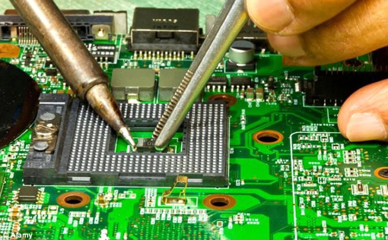
Inspection strategy has to grow with the order. Solder paste inspection catches printing defects before they hide, automated optical inspection finds placement errors, and X-ray exposes joints that cannot be seen from outside. Functional test then confirms that the assembled board behaves as a system rather than as a collection of good looking parts.
A single supplier that handles both board fabrication and board level test avoids the most common failure mode in a robot program, which is a defect that appears after the board leaves one factory and before it enters another. That handoff is where information is most easily lost.
Consistency Between Board Fabrication and Assembly
Robots need many board types, so the handoff between fabrication and assembly happens dozens of times per program. Each handoff adds a chance for a stack up to be misread, a surface finish to be mismatched or a panel to be baked in a way that affects solderability. Fewer handoffs means fewer surprises.
Board fabrication and assembly under one quality system also speeds up problem solving. When an assembly defect appears, the trace data from the fabrication side is already available, and root cause analysis can begin the same day instead of waiting a week for a supplier response.
What Buyers Should Ask Before Committing
Purchase decisions in this market are often made on price per square meter, which is the least informative number available. A more useful question is how the supplier handles change: how a stack up revision is quoted, how a new board type is introduced into production and how quickly a yield problem is reported.
Buyers should also ask which processes are run in house. Microvia plating, heavy copper, controlled impedance and flexible circuit lamination are the four capabilities that decide whether a robot program can be supported end to end. Any of them outsourced introduces a supply risk during a ramp.
Package Choice Shapes the Board Behind It
Component packages decide a large part of the routing problem. A processor in a fine pitch ball grid array may demand microvias, while the same function in a larger package can often be routed on a conventional multilayer board. Engineers who model both options usually find that package selection moves cost faster than layout effort does.
Suppliers see the consequence first. A late change of package can force a new stack up, a new stencil and a new reflow profile, which resets process learning on that board. Involving the factory while the package is still a choice, rather than a decision, keeps that reset from happening at all.
Materials Are a Supply Decision as Much as an Electrical One
High frequency materials, low loss laminates and specialised adhesiveless flex base films are produced by a small number of suppliers, and their lead times move with demand from data centre and automotive programs. A robot program that specifies a scarce material without checking availability can lose weeks before the first panel is laminated.
Good practice is to qualify two materials for each board and to confirm both before the ramp begins. Sourcing and fabrication should agree on the alternatives together, because an approved substitute that the factory cannot process reliably is not really an alternative at all.
Where the Supply Chain Value Moves
As humanoid manufacturing scales, the value of ordinary capacity does not rise much. What rises is the value of suppliers who can handle HDI, power, flexible and mixed technology boards inside one program while holding yield and batch consistency steady. That combination is what the manufacturing process has to deliver.
The robot industry will need many such suppliers. Programs are already measured in thousands of units per week, and every one of them depends on electronics that must be identical from the first unit to the last. That requirement, rather than any single order announcement, is what will reshape the PCB supply chain over the next few years.