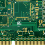
PCB Warpage in Manufacturing – Causes, Impact & Proven Solutions
In PCB manufacturing, board flatness directly affects product quality, assembly efficiency, and long‑term reliability. With the trend toward higher density, miniaturisation, and high performance, PCB warpage has become a critical issue in design, fabrication, and SMT assembly.
Whether in consumer electronics, automotive, industrial controls, or medical devices, excessive warpage leads to placement errors, soldering defects, BGA failures, and reduced reliability. Understanding the mechanisms of warpage and implementing effective countermeasures is essential for improving yield and lowering production costs.
1. What Is PCB Warpage?
PCB warpage is the bending, twisting, or distortion of a printed circuit board due to unbalanced internal stress during manufacturing or assembly, causing the board to deviate from its designed plane.
It is usually expressed as a warpage percentage:
Warpage (%) = (Maximum deviation ÷ Board diagonal length) × 100%
Higher percentages indicate more severe deformation.
Bow vs. Twist vs. Combined
- Bow: a cylindrical bending along one axis, common when one side has uneven stress.
- Twist: a diagonal saddle‑shape deformation where corners are not coplanar, often seen in large multilayer boards.
- Bow & Twist combined: the most common form in production.
Industry Standards (IPC)
- Bare board: ≤0.75%
- SMT assembled board: ≤0.50%
- High‑density BGA boards: ≤0.30%
Exceeding these limits causes serious placement and soldering issues.
2. Main Causes of Warpage in PCB Manufacturing
2.1 Material Factors
- CTE mismatch: different thermal expansion rates between copper, resin, and glass fibre generate internal stress during heating.
- Core/prepreg mismatch: improper pairing of core and prepreg materials in multilayer lamination leads to layer‑to‑layer stress.
- Moisture absorption: FR4 absorbs moisture; during reflow, rapid vaporisation creates internal pressure, causing deformation.
2.2 Design Factors
- Unbalanced copper distribution: e.g., 80% copper on top vs. 25% on bottom – differential expansion causes bending.
- Asymmetric stack‑up: uneven layer arrangements concentrate stress and increase warpage.
- Large solid copper areas: localised cooling differences create localised warpage.
- Insufficient board thickness: ultra‑thin boards (0.4–0.8 mm) are much more prone to deformation than standard 1.6 mm boards.
2.3 Manufacturing Process Factors
- Lamination conditions: temperature, pressure, and heating/cooling profiles affect residual stress.
- Machining (drilling/routing): mechanical processes can release residual stress, especially in large boards.
- Surface finish processes: HASL (hot air solder leveling) involves high temperature and molten solder, often increasing warpage risk compared to ENIG or OSP.
3. Impact of PCB Warpage on Electronic Products
- SMT assembly defects: poor paste printing, inconsistent paste thickness, component shift, and reduced placement accuracy.
- Soldering reliability issues: BGA head‑in‑pillow, open joints, cracked solder balls, and intermittent connections – especially critical in automotive and industrial applications.
- Increased manufacturing costs:
- SMT rework: $0.5–5 per board
- BGA rework: $20–100 per component
- Production line downtime: hundreds to thousands of dollars
- Customer returns: significant financial and reputational loss
4. Common Types of PCB Warpage
- Bow (single‑direction bending)
- Twist (diagonal spiral deformation)
- Combined bow & twist
- HDI warpage – due to microvias, thin cores, and high layer counts, HDI boards are especially susceptible.
5. Warpage Inspection Methods
- Visual inspection: quick screening
- Flatness gauge: production‑line measurement
- 3D optical measurement: laser scanning or profilometry for high‑accuracy data (equipment cost: $5k–$150k+)
- IPC calculation formula: (max height / diagonal) × 100%

6. Design Strategies to Reduce Warpage
- Symmetric stack‑up: mirror copper thickness and dielectric layers (e.g., 8‑layer board with balanced construction).
- Balanced copper distribution: keep copper area difference between layers within 10%.
- Choose adequate board thickness: 1.0 mm, 1.2 mm, 1.6 mm, or 2.0 mm – thicker boards are more rigid.
- Avoid large empty areas: use copper thieving to improve thermal uniformity.
- Select high‑stability materials: high‑Tg (170°C+) materials offer better dimensional stability than standard FR4.
For expert guidance on stack‑up and layout, visit our PCB design & layout service.
7. Process Controls to Minimise Warpage
- Optimised lamination: precisely control heating rate, pressure profile, and dwell time to reduce residual stress.
- Stress‑relief baking: typically 105–125°C for 2–6 hours to remove moisture and relax internal stress.
- Controlled cooling: slow, uniform cooling prevents thermal shock.
- In‑line quality monitoring: AOI, X‑ray, flatness checks, and SPC (statistical process control) ensure consistent warpage control.
8. Warpage During SMT Reflow
Lead‑free reflow peak temperatures reach 245–260°C, causing transient deformation. Repeated thermal cycling increases warpage risk. Using support fixtures (costing $50–2,000) can help maintain flatness during reflow.
For reliable SMT assembly, consider our SMT PCB assembly services, which include warpage mitigation measures.

9. Material Selection and Warpage Resistance
- Standard FR4 (Tg 130–140°C) – moderate
- High‑Tg FR4 (Tg 170–180°C) – good
- Low‑CTE materials (Tg >180°C) – excellent
Cost reference (prototype):
- 2‑layer: $5–20
- 4‑layer: $20–80
- High‑Tg: $50–200
- HDI: $150–1000+
- High‑frequency: $200–2000+
Actual prices vary by size, layer count, material, and quantity.
10. gopcb’s Comprehensive Warpage Control Solutions
As a professional PCB manufacturer, gopcb has established a robust quality system to control warpage throughout the production cycle.
- Advanced stack‑up optimisation: copper balance analysis, material matching, and symmetric construction.
- Precision lamination: state‑of‑the‑art equipment ensures uniform temperature and pressure, minimising layer stress.
- Automated flatness inspection: every batch is verified to meet customer warpage requirements.
- High‑reliability capabilities: HDI, high‑frequency, automotive, industrial, medical, and multilayer PCBs.
Whether you need prototyping or volume production, gopcb delivers low‑warpage, high‑reliability PCBs. Explore our PCB manufacturing and turnkey assembly solutions for end‑to‑end support.
11. Conclusion
PCB warpage is a critical factor affecting manufacturing quality and product reliability. Its causes span material properties, design choices, process parameters, and assembly conditions. By implementing symmetric stack‑ups, balanced copper, high‑Tg materials, and rigorous process controls, warpage can be significantly reduced – improving yield, lowering costs, and enhancing long‑term reliability.
For high‑reliability projects, partnering with an experienced manufacturer like gopcb – with advanced equipment, mature warpage control techniques, and multilayer expertise – ensures low‑warpage, high‑quality PCBs for automotive, industrial, medical, and other demanding applications.
Get started with our prototype PCB assembly or high‑volume assembly services to bring your designs to production with confidence.