PCBA Assembly Line Equipment: What a Complete SMT Line Includes
A PCBA assembly line is not a single machine but a sequence of processes that each add one controlled layer of quality to the board. Every station has a different job, and the output of the first station becomes the input constraint of the next. Understanding that chain is what lets a design team predict yield, cost and lead time before the first order is placed.
The typical sequence runs from solder paste printing through placement, reflow, and then inspection. Support equipment handles material storage, cleaning, rework and drying. The exact configuration changes with volume, board mix and automation level, but the underlying physics of each step does not.
What an Assembly Line Actually Controls
An SMT line exists to place a known amount of solder and a known component at a known position, then form a reliable joint without damaging either part. Three variables dominate: paste volume, placement accuracy and thermal profile. If any one drifts, defects appear downstream and are usually attributed to the wrong station.
This is why line configuration matters to designers. A line built for high-mix, low-volume work tolerates wide component ranges and frequent changeovers. A line built for one product optimizes speed. The same design can pass on one and fail on the other.
Solder Paste Printing Sets the Yield Ceiling
Paste printing is the first and most influential step. A squeegee pushes solder paste through a laser-cut or electroformed stencil onto the pads. Aperture design, stencil thickness, squeegee pressure, print speed and separation speed all determine how much paste lands on each pad.
For fine pitch work, the stencil is usually 0.10 to 0.12 mm thick with an area ratio above 0.66. Apertures are often reduced slightly in width and lengthened in the paste release direction to improve transfer. Prints that look acceptable by eye can still deposit 30 percent more paste on one side of the board than the other, which shows up later as bridging or as opens on a different part of the panel.
Solder paste printing is measured continuously on modern lines. A solder paste inspection machine samples paste height and volume in line, and the printer adjusts pressure or cleaning frequency from that data. Without measurement, the printer becomes the largest uncontrolled variable in the whole process.
Placement: Speed Versus Flexibility
A pick and place machine takes components from feeders and places them at programmed coordinates. Placement accuracy is expressed in microns at a stated throughput, and the two numbers trade off against each other. Chip shooters place small passives at very high rates; flexible mounters handle fine-pitch ICs, connectors and odd-form parts more slowly.
A practical PCBA assembly line combines both. One or two high-speed heads place 0402 and 0603 passives, and a general-purpose machine handles the larger devices. Placement programs include vision alignment for fine-pitch parts, nozzle selection by component class and feeder setup that matches the reel sizes actually stocked.
Placement force matters more than many designers expect. Excessive downward force during placement pushes paste sideways and is a common root cause of component shift during reflow. Pad geometry, paste volume and nozzle choice all interact here, and the assembly team is the right group to consult when a shadowed or asymmetric pad is unavoidable.
Reflow Soldering and Profile Control
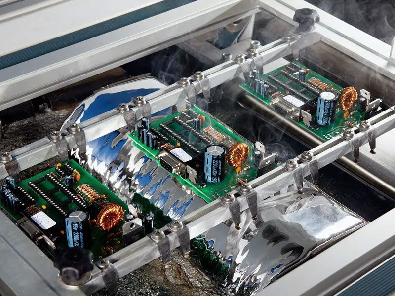
Reflow soldering turns printed paste and placed parts into electrical joints. The board travels through preheat, soak, reflow and cooling zones. Peak temperature is normally 10 to 30 degrees Celsius above the alloy liquidus, with time above liquidus kept short to limit intermetallic growth and thermal damage.
SAC305 alloy melts near 217 degrees Celsius, so a peak of roughly 235 to 245 degrees Celsius is typical. The profile is measured with thermocouples attached to representative boards, including a large thermal mass location and a small one. Nitrogen atmosphere reduces oxidation on fine-pitch assemblies and improves wetting on OSP-finished pads.
Reflow soldering is also where asymmetrical designs punish the process. If one side of a small component has far more copper than the other, the two ends heat at different rates and the part stands up or slides. Adding thermal relief, balancing pad copper or adjusting the soak profile are the usual corrections.
<img src="https://www.gopcba.com/wp-content/uploads/2026/08/high_density_pcb.jpg" alt="Automated optical inspection station on an SMT assembly line” />
Wave and Selective Soldering for Through-Hole Parts
Boards that combine SMT and through-hole connectors need a second soldering step. Wave soldering passes the board over a molten wave after fluxing and preheating. It is fast but exposes the whole assembly to heat, so sensitive parts are often masked or hand soldered instead.
Selective soldering uses a small nozzle or a focused laser to solder individual joints. It costs more per joint but allows mixed-technology assemblies to be built without hand soldering every pin. Both processes need adequate thermal relief on through-hole pads, otherwise the hole fails to fill or the pad lifts.
Inspection: SPI, AOI and X-ray
Automated optical inspection compares a camera image of each board against a programmed reference, flagging missing parts, tombstoning, wrong polarity, insufficient solder and bridging. Modern systems learn the acceptable variation of a good board, which reduces false calls on textured or reflective surfaces.
X-ray inspection is used for ball grid arrays, chip-scale packages and any joint hidden under a package body. It reveals voids, insufficient ball collapse and head-in-pillow defects that optical inspection cannot see. For automotive and medical work, X-ray plus cross-section sampling is common.
Inspection data is only useful if it feeds back. A spike in one defect class should change a printer parameter or a placement program, not simply generate more rework. That feedback loop is what separates a controlled process from a line that is merely busy.
Support Equipment That Decides Uptime
Ancillary equipment determines how long the line runs without interruption. Solder paste is stored cold and warmed to room temperature before use, typically over four hours. Feeders are loaded and verified off line so changeover time drops. Board handling conveyors, buffers and loaders keep parts moving without manual transfer.
Cleaning equipment matters for boards with flux residues that must be removed, especially where conformal coating follows. Rework stations with hot air, preheaters and microscopes handle the small percentage of boards that need rework. None of these stations add value, but their absence stops the line.
Line Types: Automation Level and Scale
Fully automated lines connect every machine with automatic board loaders, buffers and unloaders so the panel flows without manual handling. Semi-automated lines leave the printer or the board transfer to an operator. The first suits stable, higher-volume work; the second survives high product variety at lower capital cost.
By scale, a large line may combine one general-purpose mounter with several high-speed machines and is aimed at a single high-volume product. Medium and small lines serve research groups and smaller manufacturers who need mixed volumes and multiple products on one shift. A dual line consists of two parallel single lines that can run independently or be linked.
Matching a Line to Your Product
Choosing a line starts from the board, not the machine list. Count fine-pitch devices, package types, board thicknesses and the annual quantity. Boards with many 0201 passives, BGA devices and press-fit connectors need vision placement, X-ray and reflow control that a simple line cannot provide.
Then examine changeover. A product that runs in small batches needs off-line feeder setup, quick-release stencils and a printer that stores recipes. A single-product program justifies dedicated feeders and higher-speed heads. Comparing these requirements against the equipment list gives a realistic picture of yield and cost before the first panel is printed.
The full sequence of steps, from bare board to tested assembly, is described in the PCBA development process. Design decisions that interact with placement and reflow are covered under placement order and pad positioning, and the defects that follow from poor paste balance are collected in SMT component shift causes.
FAQ
How many machines does a minimum viable SMT line need? A printer, one placement machine and one reflow oven can build simple single-sided boards. Adding a second placement machine and an automated optical inspection station raises throughput and catches defects earlier, which usually pays back faster than another printer.
Why does the same design yield differently at two suppliers? Paste printing, placement force and the thermal profile are process parameters, not design parameters. Two lines with different stencil thickness, nozzle sets or conveyor speed will produce different results from identical Gerber data.
Is a semi-automated line acceptable for small batches? Yes. For mixed product runs of a few hundred boards, a semi-automated line with manual loading and a strong inspection step often gives better economics and comparable quality than a fully automated line that must be reconfigured constantly.