Ultra-Thin Flexible PCB: Construction and Handling Limits
An ultra-thin flexible PCB solves problems that rigid boards cannot: a sensor in a moving assembly, a display folded inside a hinge, or a cable replacement that must survive millions of flex cycles. The thinner the construction, the better it bends, and the less forgiving it becomes at every stage from design to assembly.
What Makes a Flexible Circuit Ultra-Thin
Total thickness is the sum of the base film, the adhesive or the direct-bond interface, the copper and the coverlay. A conventional flexible circuit may be 100 to 150 microns thick, while an ultra-thin construction can be half of that, achieved by removing adhesive layers and reducing the film and copper thickness.
The benefit is mechanical. Bending stress is proportional to thickness, so halving the thickness roughly halves the strain at a given bend radius. That translates into a tighter allowable radius, a longer fatigue life in dynamic applications, or both.
Adhesiveless Laminate Construction
Traditional flexible laminates bond copper to polyimide with an acrylic or epoxy adhesive. The adhesive is thicker, softer and less thermally stable than the film, and it dominates the fatigue behaviour of a thin construction.
An adhesiveless laminate deposits or laminates copper directly onto the polyimide, eliminating that layer. The result is thinner, more flexible, better able to survive high temperature and more dimensionally stable during processing. For ultra-thin designs it is generally the required starting point.
Coverlay Options and Thickness
The coverlay protects the conductors and defines the exposed pads. A conventional coverlay is a polyimide film with its own adhesive layer, which adds to the total thickness. Thin variants use a thinner film with a thin adhesive, and photoimageable coverlays can be developed like a resist, which allows smaller openings and avoids the tolerance stack of a punched or drilled film.
Where the construction must be as thin as possible, some designs omit the coverlay entirely and rely on a surface finish plus selective plating for protection. That saves thickness but leaves the conductors exposed to mechanical damage and to the environment, so it is limited to protected applications.
Bend Radius and Dynamic Flexing
Bend radius is specified as a multiple of total thickness, and the multiple depends on whether the bend is static or dynamic. A one-time bend tolerates a much tighter radius than a bend that must survive repeated motion.
The orientation of the conductors relative to the bend line matters more than any other geometric factor. Traces should cross the bend perpendicularly so that the copper bends along its length, and any plated through hole, stiffener or rigid area placed inside the bend becomes a stress concentrator and a likely failure point.
Stiffeners and Termination Areas
Connectors and component sites need a rigid surface, which is provided by a stiffener bonded behind the pad area. Stiffeners are usually polyimide or FR-4, selected for thickness and thermal expansion compatibility with the flexible substrate.
Stiffener placement is a design decision with mechanical consequences. It must end outside the intended bend region, and its edge should not create an abrupt stiffness transition, because that edge becomes the point where a flexing cable eventually cracks.
Impedance Control on Thin Constructions
Controlling impedance on a thin flexible circuit is possible and increasingly common, but the geometry is different from a rigid board. The dielectric is thinner, so a 50 ohm microstrip may require a narrower trace than a designer expects, and copper thickness tolerances have a proportionally larger effect.
A reference plane can be added as a separate layer with a thin dielectric above it, which gives a controlled structure at the cost of thickness. Where the requirement is only to reduce crosstalk rather than to hold a precise impedance, wider spacing and a ground pour on the same layer is often enough.
Handling and Assembly Constraints
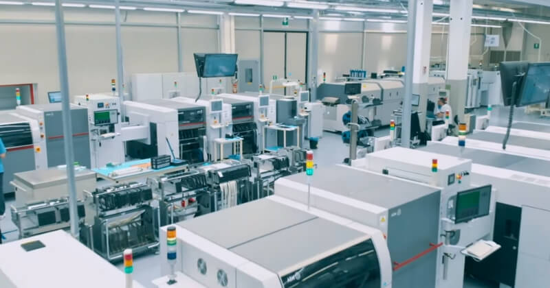
Ultra-thin circuits are difficult to handle in automated assembly. They curl, they are sensitive to static, and they cannot be supported by a conventional conveyor without a carrier. Many processes require the parts to be supplied on a rigid carrier frame and depanelised after assembly.
Reflow temperature is also a constraint, because the thin construction has less thermal mass and the polyimide loses dimensional stability as it approaches its glass transition. Where components must be attached, the process window is narrower than for a rigid board and the panel support becomes part of the design.
Reliability Testing
Flexible circuits are qualified by bending, not by inspection. A dynamic application should be tested with a repeated flex fixture at the specified radius, and the test should continue well beyond the expected service life so that a marginal design fails in the laboratory rather than in the field.
Thermal cycling and humidity exposure are often combined with the flex test, because moisture uptake changes the mechanical properties of polyimide. The test plan should reflect the actual environment, and the guidance on conformal coating and protection is worth reviewing where the assembly is also exposed to contamination.
Where Ultra-Thin Flexible Circuits Are Used
The typical applications are compact and mechanically demanding: camera modules and their interconnects, foldable display hinges, medical catheters and endoscopes, hearing instruments and wearable sensors. In each case the circuit fits where a rigid board cannot and moves where a cable would fail.
Outside those cases, a standard flexible circuit or a rigid-flex construction is usually a better balance of cost and robustness. The decision should be driven by the mechanical envelope and the cycle count, and the stackup then reviewed against fabrication practice for the specific construction.
Panelisation and Depaneling for Thin Circuits
Ultra-thin circuits are almost always processed on a carrier. The fabricator laminates or tapes the thin circuit to a rigid frame, keeping it flat through assembly and test, and the parts are separated afterwards. Designing the panel with that process in mind avoids a situation where the circuit must be handled loose before it is ready.
The separation method matters. Laser cutting and die cutting both produce clean edges without the mechanical stress that routing or punching would impose on a thin film, and the choice depends on volume and on how close the cut runs to a conductor.
Tabs connecting the circuit to its frame should be placed away from bend regions and sized so that the remaining nub does not interfere with the enclosure. Marking the bend line on the panel silkscreen, or moulding a guide into the housing, gives the assembly operator a defined target rather than a judgement call.
FAQ
How thin can a flexible circuit actually be? Constructions below 50 microns total thickness are available, but they require careful handling and often a carrier for assembly. The practical limit for a product is usually set by the assembly process rather than by the material.
Can ultra-thin circuits carry high-speed signals? Yes, with a controlled-impedance structure and a reference plane, though the thin dielectric makes the geometry delicate. Where the signals are moderate, keeping traces short and spacing them from neighbours is often sufficient.
Do thin circuits need a stiffener at every connector? Every area that a connector clamps should have a stiffener, or the contacts will bear on a surface that flexes and the connection becomes intermittent. The stiffener must sit outside the bend zone, as described in board outline and mounting design.