Analog and Digital Ground Separation in Mixed Designs Once a design contains an ADC beside a switching clock, the question of how to treat analog and digital ground comes up in every review. The conventional answer is to split the two and tie them at one point, but the split…

PCB Layout Anti-Interference Design: Rules for Noisy Systems Interference problems are almost never solved by adding components. They are solved by removing the loops and discontinuities that allow noise currents to travel through the board. Anti-interference design starts with ground, continues with power distribution, and finishes with the placement of…
PCB Prototyping to Full Product Design: The Complete Flow Most descriptions of the design process treat it as one long sequence. In practice it splits into two stages with different goals, different people and different tools. PCB prototyping is exploratory work done by the engineer who understands the application. Product…
Non-Isolated Switching Supply PCB Layout: Rules That Matter A prototype power board that works quietly and runs cool on the first power-up is a rare outcome. More often the board functions, but the switching waveform jitters, a magnetic component buzzes in the audio band, or the output carries ripple that…
Differential Impedance Design Guide for Two- to Six-Layer Stackups Differential impedance is a fabrication requirement disguised as a layout preference. The traces on the screen are only a proposal; what the receiver sees depends on the dielectric, the copper thickness and what the etcher actually produces. Agreeing on numbers before…
Aerospace PCB Design: Layout Rules That Keep Avionics Reliable An aerospace PCB is asked to do something ordinary boards are never asked to do: keep working while the environment tries to destroy it. Vibration, wide temperature swings, low pressure, humidity and salt fog all act on the same assembly, and…
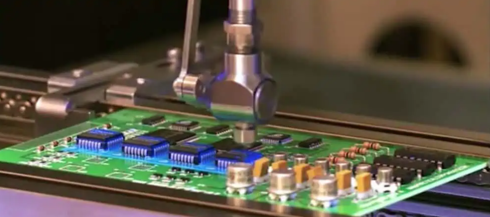
PCBA Assembly Line Equipment: What a Complete SMT Line Includes A PCBA assembly line is not a single machine but a sequence of processes that each add one controlled layer of quality to the board. Every station has a different job, and the output of the first station becomes the…
Single-Point Grounding vs Multi-Point Grounding Grounding is the least glamorous part of a schematic and the part that decides whether a product passes electromagnetic compatibility testing. A ground system does three jobs at once: it protects people from fault current, it provides the stable zero-volt reference that every signal is…
Layer Stack-Up Strategy for EMI Shielding Most engineers treat the layer stack as a mechanical necessity, but on a fast board it is also the main electromagnetic component. The planes, their spacing and their order decide how much energy leaves the board, how clean the power delivery network is, and…
PCB Stack-Up Design Guide for Multilayer Boards A stack-up is the drawing that fixes how many copper layers a board has, how thick each dielectric is, and which layer carries signals, power or ground. It is written long before the first trace is routed, and almost every later decision depends…