Castellated Holes: Key Checks Before Release
A module that solders down like a component depends on castellated holes that are drilled, plated and then cut in half, leaving a plated channel on the board edge. The whole process is a study in working at a boundary: every parameter has to be right at the cut line, where the board ends and the barrel becomes a surface.
What Castellated Holes Are Used For
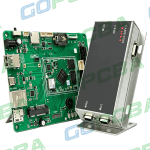
Castellations let a small module be reflowed onto a carrier without a connector, which saves height and cost on products where the module sits permanently. The same feature appears on radio modules, sensor packages and power bricks. Because the joint is formed on the outside of the board edge, the half-hole has to be plated, solderable and mechanically strong after the profile has been routed.
The design brief is therefore electrical and mechanical at once. The castellation carries current between two boards, and it also takes the peel and shear load of the module during handling. A castellation that is plated but thin, or plated but burred, passes a visual check and fails in the field. The acceptance criteria should therefore be written as numbers on a drawing: finished hole diameter, plating thickness at the cut face, maximum burr height and the routing depth tolerance.
Drill Diameter and Finished Hole Size
Castellated holes are usually drilled between 0.6 mm and 1.0 mm finished, and the drill is chosen so the finished diameter after plating sits in that window. The cut removes roughly half the barrel, so the remaining channel is a half cylinder with a plating thickness that must be sufficient on its own, not merely adequate for a full barrel.
A castellation that is too small cannot be probed or soldered reliably, and one that is too large weakens the edge and removes too much laminate between adjacent holes. Pitch follows the same logic: modules commonly use 1.0 mm or 1.27 mm centres, and the pitch determines how much material remains between castellations after routing.
Plating Thickness in a Half Barrel
Plating in a castellation is measured on the cut face, and a minimum of 20 to 25 microns of copper in the barrel is the usual target for boards that will see thermal cycling. Because the cut exposes the plating in cross-section, thin plating is visible as a bright band with almost no thickness and shows up immediately on a microsection.
Current carrying capacity should be calculated from the half-barrel cross-section rather than the nominal hole size, since the cut removes half the copper. Where a castellation carries significant current, specify the finished copper thickness and verify it by section rather than assuming the plating bath produced the same result in a partial barrel as in the rest of the panel.
Routing Depth and the Cut Through the Barrel
The router cuts along the hole centreline, and depth control is the critical tolerance. Cut too shallow and the castellation is a closed hole with a slot in front of it; cut too deep and the barrel is removed entirely, leaving only laminate. A typical tolerance is plus or minus 0.05 mm on the depth of cut relative to the hole axis.
Router bit diameter sets the width of the cut and therefore how much of the barrel survives. A worn bit cuts a narrower kerf and leaves a burr that later flakes, so bit life should be logged and bits replaced on a count rather than on visible wear. Cutting in multiple shallow passes produces a cleaner wall than one deep pass.
Burrs and Smearing at the Castellated Edge
The cut leaves copper burrs on the edge of the castellation, and a burr that survives finishing will sit between the module and the carrier pad and hold the joint open. Acceptance for a castellation edge is measured in tens of microns: burrs above roughly 25 microns should be rejected or removed, because they interfere with the solder fillet and can bridge to the adjacent hole.
Smearing is the mirror problem. A dull bit smears resin across the plating instead of cutting it cleanly, which looks like a dark film on the cut face and blocks solderability. Both defects are reduced by the same measures: sharp tooling, correct feed rate, and a deburr step before the surface finish is applied.
Solderability of the Castellation After Finish
Whatever finish covers the board covers the castellation, and the finish has to reach into a half barrel that is open on one side. Electroless nickel and immersion gold covers the exposed plating well when the barrel is clean; hot air solder leveling can fill or web the castellation and is usually avoided on fine-pitch modules. Where the finish is uneven, wetting on the cut face is poor even when the rest of the pad wets normally.
Solderability should be verified by a wetting or dip test on a sample from each lot rather than assumed from the finish specification. Castellations are also easily contaminated by handling during depaneling and packing, so the test sample needs to go through the same handling path as production parts.

Edge Plating on the Board Perimeter
Where the whole perimeter is plated rather than individual holes, the process changes: a conductive seed is applied to the edge, then the panel is plated in the same bath as the barrels. Edge plating of 20 to 25 microns is common for shielding and for grounding modules into a carrier, and the plating has to be continuous around corners without voids or thin spots at the panel edge.
Continuity is verified by sectioning the edge at several points and by a resistance check between the edge plating and the ground net. Corners and tab-routed sections are where the plating thins or breaks, because the seed coverage is worst there and the routing leaves a slightly different surface.
Inspection: Cross-Section and Visual Criteria
Inspection combines a visual check under magnification with a microsection. Visually, look for a plated half barrel with a continuous wall, no burr above the limit, no smear, and no gap between the plating and the laminate. On section, measure the plating thickness at the cut face and check for voids or cracks along the barrel.
Recording the measurement position matters, because plating thickness varies along a barrel and around a panel. Sample the same location each time, and sample more than one castellation per panel edge so a single good hole does not mask a systematic problem.
Panel Layout, Rails and Handling
Castellated modules are usually routed from a panel with rails, and the rails must hold the module until the last operation. Every cut that creates a castellation also weakens the panel, so the layout has to keep enough material for handling. V-score is unsuitable here because it does not produce the clean half-hole edge that routing does.
After routing, the parts are separated, and the exposed plating is vulnerable to fingerprints and to the packing material. Handle modules by their faces, use clean gloves, and pack so the edges do not rub against each other, otherwise a good castellation becomes an unsolderable one before it reaches the customer. Keep the interval between routing and packing short, because an exposed copper edge oxidizes quickly even under a good finish.
FAQ
What plating thickness should a castellation have? Treat 20 to 25 microns of copper in the barrel as the minimum and verify it on a microsection, because the cut exposes half the barrel and the remaining half carries the current.
Why is routing depth so critical for castellations? The cut must follow the hole axis within about plus or minus 0.05 mm. Shallower leaves a closed hole, deeper removes the barrel and leaves bare laminate.
Which surface finish suits castellated modules? Electroless nickel and immersion gold covers the exposed half barrel cleanly. Hot air solder leveling can web or fill the castellation and is usually avoided on fine pitch.