Cockpit-Driving Fusion PCB: When Two Controllers Become One
On 26 August 2026 Chery launched the Fengyun T7, and with it a cockpit-driving fusion platform from Desay SV entered mass production for the first time. The design runs the cabin system and the driver assistance system on a single Qualcomm SA8775P processor built on a four nanometre process with seventy two TOPS of neural processing capacity. The supplier reports that cross domain data latency fell by more than ninety percent and memory bandwidth use dropped by nearly half compared with separate controllers. What makes the launch notable for the board industry is the price band, because a cockpit-driving fusion PCB that was previously a premium feature is now arriving in cars costing around one hundred thousand yuan.
A cockpit-driving fusion PCB is the physical result of that decision. Two architectures that used to occupy separate enclosures now share one board, and the routing, power and thermal load that were distributed between them are concentrated in a single stack up that still has to fit the same vehicle package and qualify to the same automotive standards.
One Box Fewer, Not One Problem Fewer
Separating the cabin and driver assistance systems had an obvious cost in hardware: two processors, two power supplies, two sets of memory and two sets of connectors and harnesses. Consolidating them removes duplication and shortens the data path between the two domains, which is exactly where the latency improvement comes from. None of the computing work disappears, however.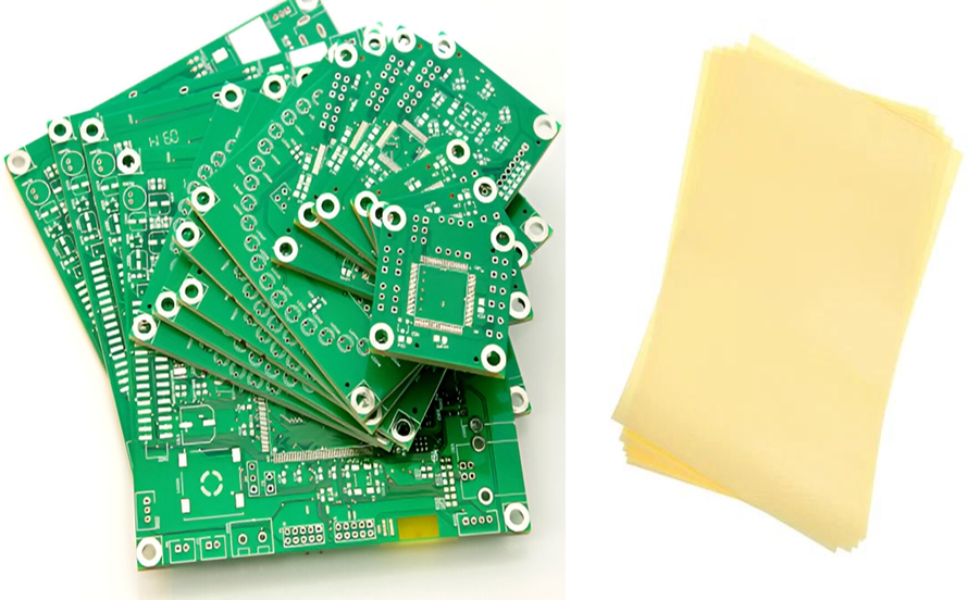
The cabin domain drives displays, audio, voice processing and connectivity, while the assistance domain consumes camera and radar data and runs perception. In a fused design both are served from one processor with shared memory and shared interfaces, so the board sees the combined net count rather than the average of two separate boards. In the Chery application that includes seven cameras, three millimetre wave radars, multiple displays and the audio system connected to one controller.
High Speed Nets and Power Nets Compete for the Same Area
Camera serial links, Ethernet, memory interfaces and processor interconnects all require controlled impedance and a continuous reference plane, and together they occupy a large share of the available routing layers. At the same time, a processor of this class draws significant current, so the power distribution network needs thick copper, wide planes and enough decoupling close to the die.
Those requirements pull in opposite directions. High speed routing wants isolation and clean references, while power distribution wants copper area and low impedance paths. The solution is a stack up that assigns specific layers to each function, with ground planes separating them and enough layer count that neither domain is forced to share space with the other. That is the reason high layer counts appear in domain controllers even when the component count would fit on fewer layers.
Where High Layer Count and HDI Earn Their Cost
A processor package with a large ball grid array cannot be routed on the surface. Every signal has to escape the package footprint, and the inner rows are only reachable through vias. Fine line routing and microvia structures allow those escapes to happen inside a few layers instead of spreading across many, which keeps the board smaller than the mechanical package allows and reduces the length of the high speed connections.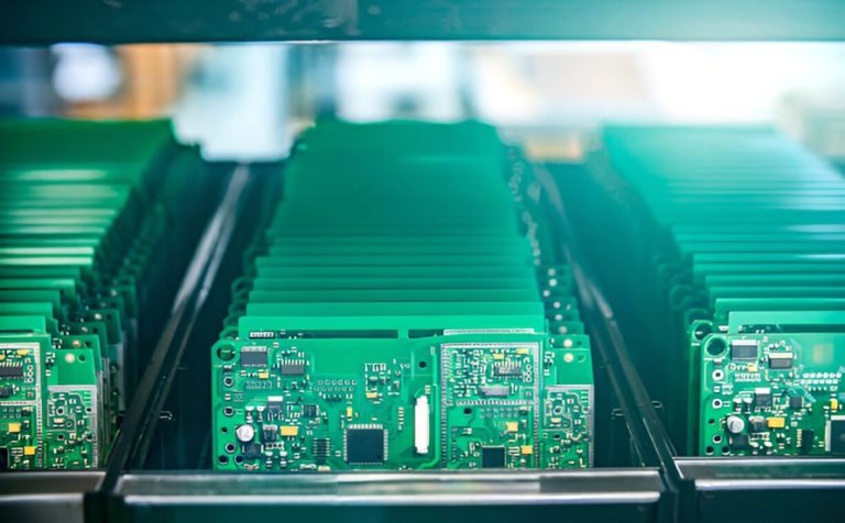
Laser drilled microvias also improve the power network, because they can be placed directly under the package to connect decoupling capacitors and power planes with short vertical paths. The trade is process complexity: more build up layers, tighter registration, and plating fill requirements that have to be controlled to avoid voids. Choosing between layer count and HDI density is therefore a manufacturing decision as much as a design preference, and it is worth discussing with the fabricator before the stack is frozen rather than after.
Lamination, Impedance and BGA Yield
Automotive domain controllers are built on thick, high layer count boards, which means several lamination cycles and accumulated dimensional movement. Registration between layers has to stay tight enough that every via lands inside its target pad, and the impedance of high speed nets has to remain inside its window after etching, lamination and plating have each contributed their variation.
Yield in this class of product is usually decided by a combination of those effects rather than by one of them. A small impedance drift may pass on its own, and a small registration error may pass on its own, but together they can push a board beyond specification. Manufacturers that build automotive high layer count products therefore track process data across all the relevant steps, which is a core part of a controlled quality system rather than an inspection activity at the end of the line.
Thermal Load From a Fused Compute Platform
Concentrating cabin and assistance computing into one device concentrates heat as well. A seventy two TOPS processor dissipates power continuously under load, and beside it sit memory devices, power stages and the interface components for cameras and displays. The board has to conduct that heat into the enclosure without distorting the electrical behaviour of the material.
Practical measures include thermal vias under the processor, copper planes tied to a defined thermal path, and careful placement of temperature sensitive components away from the hot region. Warpage then becomes a concern, because a large package on a thick board with uneven copper distribution will bend when it is heated during reflow, and a bent board risks incomplete ball connections. Balanced copper distribution and controlled lamination parameters are the usual answers, and they have to be designed in rather than corrected at assembly.
Assembly and Inspection in the PCBA Stage
The assembly stage for a domain controller combines a large fine pitch processor, memory packages and hundreds of small components on one panel. Solder paste printing has to deliver the right volume for both the large thermal pads under the processor and the tiny pads beside it, which generally means a stepped stencil and a carefully developed reflow profile.
Inspection then has to look for defects that optical methods cannot see. X-ray verifies the ball connections under the package and can detect voids in thermal pads, while automated optical inspection covers the visible joints and placement errors. Functional testing at the end confirms that the camera links, display outputs and network interfaces all work at speed, and it is the step that reveals the interference problems that only appear when subsystems operate together. Keeping fabrication and PCBA testing coordinated makes the diagnosis of those failures far faster.
Holding Parameters Constant in Volume
The difference between a demonstrable design and a shippable one is repetition. Automotive customers require evidence that layer registration, impedance, board thickness and solder joint quality stay inside their limits across production lots, not only on the first articles. That evidence comes from process capability data and from traceable records for each batch.
It also requires change control. A material substitution made to protect a delivery date can shift the dielectric constant and disturb impedance on a high speed net, so any change has to be assessed against the qualified configuration before it is introduced. Manufacturers that supply this industry usually handle that assessment as part of their production process, and customers should expect to see it described rather than assumed.
What Descending to Mainstream Cars Means
Fused cockpit and driving controllers have existed in premium vehicles for several years. Their arrival in the hundred thousand yuan segment signals that the architecture has become cost effective, and that the boards inside it are now a volume automotive product rather than a flagship demonstrator.
For board manufacturers the implication is scale combined with discipline. Volumes in this segment are large enough that yield differences translate directly into cost, and quality expectations are high enough that a process excursion is expensive. Suppliers who already build high layer count and HDI boards for automotive programmes are the natural candidates, and buyers should evaluate them on the capability that matters to this product rather than on general capacity.
Connectors, Harnesses and the Interface Budget
Removing one controller removes one enclosure and one harness, but the connector count on the remaining board rises because everything that was distributed between two units now terminates in one place. Camera links, radar inputs, display outputs, network and power all arrive at the same edge, and each interface brings requirements for shielding, strain relief and mechanical retention.
Connector placement is therefore part of the signal integrity problem rather than a mechanical afterthought. A connector that forces a high speed pair across a plane split, or that routes a sensitive input beside a switching supply, will cause problems that no amount of tuning at the silicon can fix. Deciding the interface positions early, before the layout is complete, is far cheaper than relocating them once the enclosure and the harness are defined.
The Engineering Lesson
Integration rarely makes a board simpler. Removing a controller removes a box, a harness and a duplicate power supply, but it adds routing density, thermal load and process coupling to the board that remains. The technical work moves from packaging to fabrication and assembly control.
That shift is why fusion architectures reward suppliers who can manage several process families at once and can show data rather than promises. For design teams, the practical advice is to define the stack up early, model the power distribution network alongside the high speed channels, and treat lamination and BGA assembly as design constraints from the first layout review. Those decisions are difficult to change once tooling exists, and they determine whether a fused controller can be built in volume at a cost the vehicle programme can accept.